MOTOR GENERATOR CONTROL COMPUTER REMOVAL

Note
-
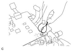
If metal shavings are created when screws are removed from the inverter with converter assembly, remove them using tape or equivalent.
-
Use non-residue type tape.
-
REMOVE INVERTER WITH CONVERTER ASSEMBLY
-
REMOVE WIRE HARNESS CLAMP BRACKET
-
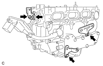
Remove the 4 bolts and 3 wire harness clamp brackets from the inverter with converter assembly.
-
-
DRAIN COOLANT (for Inverter)
CAUTION:
Wear insulating gloves.
-
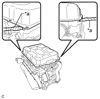
Apply protective tape to the areas shown in the illustration without leaving any gaps between the tape and part.
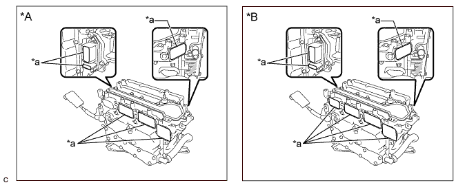
Text in Illustration *A for 2WD *B for AWD *a Protective Tape - - Note
Use non-residue type tape.
-
Tilt the inverter with converter assembly back and forth to drain the coolant (for inverter).
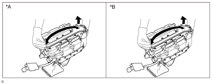
Text in Illustration *A for 2WD *B for AWD Note
Do not hold the inverter with converter assembly by the coolant pipes or inverter signal connector.
-
Blow compressed air into the inverter with converter assembly until most of the coolant (for inverter) is blown out.
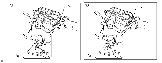
Text in Illustration *A for 2WD *B for AWD *a Coolant Pipe - - Note
Do not damage the coolant pipes.
Tech Tips
-
Use a piece of cloth as shown in the illustration to prevent the coolant (for inverter) from spraying.
-
Cover the air inlet port with a piece of cloth to minimize air leakage.
-
-
-
CLEAN INVERTER WITH CONVERTER ASSEMBLY
CAUTION:
Wear insulating gloves.
-
Using a piece of cloth, clean the outside of the inverter with converter assembly and around the bolts.
Note
To prevent foreign matter from entering the inverter with converter assembly, make sure that the protective tape is not partially removed.
-
-
REMOVE INVERTER TERMINAL COVER
CAUTION:
Wear insulating gloves.
-
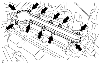
Remove the 11 bolts and inverter terminal cover.
Note
Make sure to pull the inverter cover straight up, as a connector is connected to the bottom of the cover.
-
-
CHECK TERMINAL VOLTAGE
CAUTION:
Wear insulated gloves.
Note
Do not allow any foreign matter or water to enter the inverter with converter assembly.
-
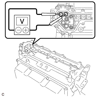
Using a voltmeter, measure the voltage between the terminals of the 2 phase connectors.
Standard Voltage 0V Tech Tips
-
Use a measuring range of DC 750 V or more on the voltmeter.
-
If it is confirmed that high-voltage is not being applied to the inverter with converter assembly, removal/installation can be performed without using insulated tools or gloves after this step.
-
-
Apply protective tape to the area that was exposed when the inverter terminal cover was removed.
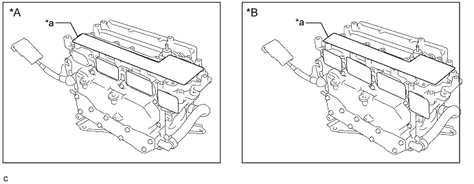
Text in Illustration *A for 2WD *B for AWD *a Protective Tape - - Note
Use non-residue type tape.
-
-
REMOVE NO. 1 INVERTER BRACKET
-
Text in Illustration *a Cloth Set the inverter with converter assembly on a clean cloth, etc. and orient it as shown in the illustration.
-
Remove the 5 bolts and No. 1 inverter bracket from the inverter with converter assembly.
-
-
HOW TO PREVENT STATIC ELECTRICITY
Note
-
Static electricity should be eliminated when removing/installing the inverter with converter assembly.
-
Do not touch the electronic components of a circuit board.
-
Keep clothes away from electronic components.
-
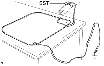
Place parts removed from the inverter with converter assembly on SST (anti-static mat).
-
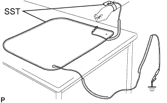
Wear SST (wrist band).
- SST
- 09890-47010
-
Connect the ground clip of the SST (anti-static mat) securely to a ground point provided in the workshop or on a workbench (anchor bolt).
- SST
- 09890-47010
Tech Tips
If the ground clip cable is too short, use an extension cable.
-
Connect the ground clip of the antistatic wrist strap securely to the specified point of the antistatic mat.
-
After removing the converter cover, perform work with bare hands to prevent damage from static electricity and entry of foreign matter.
-
-
REMOVE CONVERTER COVER
-
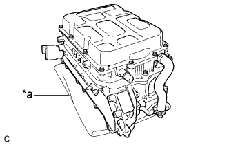
Text in Illustration *a Cloth Set the inverter with converter assembly on a clean cloth, etc. and orient it as shown in the illustration.
-
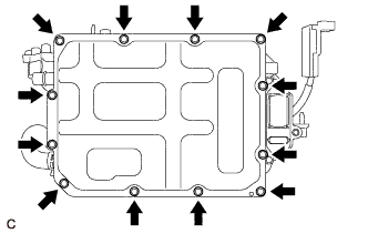
Remove the 12 bolts.
-
Text in Illustration *a Protective Tape Using a screwdriver with its tip wrapped with protective tape, remove the converter cover from the inverter with converter assembly.
-
-
REMOVE SEAL PACKING
Note
-
Only remove seal packing which is uneven, has peeled off or seeped out from between the contact surfaces.
-
Do not drop seal packing into the inverter with converter assembly.
-
Do not touch the electronic components of the circuit board.
-
Do not allow any foreign matter or water to enter the inverter with converter assembly.
-
Set the inverter with converter assembly on a clean cloth, etc. and orient it as shown in the illustration.
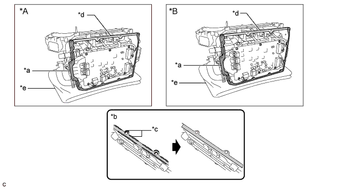
Text in Illustration *A for 2WD *B for AWD *a Seal Packing to be Removed *b Minimum Requirement for Removal of Seal Packing *c Seeped Out or Uneven Seal Packing *d Seal Packing not to be Removed *e Cloth - - -
Using a finger or a scraper with its tip wrapped with protective tape, remove any seal packing which is uneven, has peeled off or seeped out from the contact surface (*a) shown in the illustration.
Note
To prevent the seal packing from entering the inverter with converter assembly, make sure to perform the following steps to remove any remaining seal packing from the part of the contact surface (*d) shown in the illustration.
-
Set the inverter with converter assembly on wooden blocks covered with clean cloths, etc. and orient it as shown in the illustration.
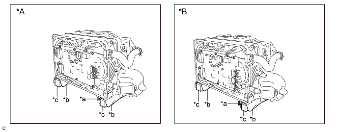
Text in Illustration *A for 2WD *B for AWD *a Stud Bolt *b Cloth *c Wooden Block - - Note
To prevent the stud bolt from being damaged, make sure to leave clearance between the stud bolt and workbench.
-
Using a scraper with its tip wrapped with protective tape or a finger, remove any remaining seal packing from around the contact surface shown in the illustration and inside the bolt holes.
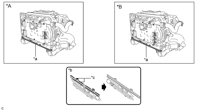
Text in Illustration *A for 2WD *B for AWD *a Seal Packing to be Removed *b Minimum Requirement for Removal of Seal Packing *c Seeped Out or Uneven Seal Packing - -
-
-
REMOVE MOTOR GENERATOR CONTROL COMPUTER
Note
-
If metal shavings are created, remove them using tape or equivalent.
-
Do not touch the electronic components of the circuit board.
-
Do not allow any foreign matter or water drops to enter the inverter with converter assembly.
-
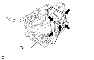
for 2WD:
-
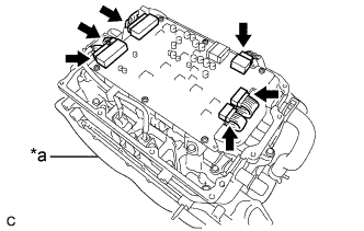
Text in Illustration *a Cloth Set the inverter with converter assembly on a clean cloth, etc. and orient it as shown in the illustration.
-
Disconnect the 6 motor generator control computer connectors.
-
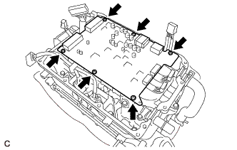
Remove the 6 screws.
-
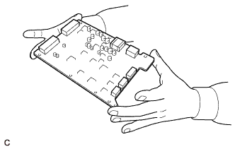
Hold the corners of the motor generator control computer and remove it from the inverter with converter assembly.
-
-
for AWD:
-
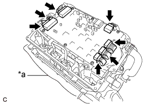
Text in Illustration *a Cloth Set the inverter with converter assembly on a clean cloth, etc. and orient it as shown in the illustration.
-
Disconnect the 7 motor generator control computer connectors.
-
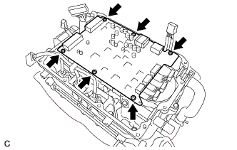
Remove the 6 screws.
-
Hold the corners of the motor generator control computer and remove it from the inverter with converter assembly.
-
-
Remove SST (wrist band).
-