HYBRID BATTERY SYSTEM, Diagnostic DTC:P0B3D-123, P0B42-123, P0B47-123, P0B4C-123, P0B51-123, P0B56-123, P0B5B-123, P0B60-123, P0B65-123, P0B6A-123, P0B6F-123, P0B74-123, P0B79-123, P0B7E-123, P0B83-123, P0B88-123, P308A-123

| DTC Code | DTC Name |
|---|---|
| P0B3D-123 | Hybrid Battery Voltage Sensor "A" Circuit Low |
| P0B42-123 | Hybrid Battery Voltage Sensor "B" Circuit Low |
| P0B47-123 | Hybrid Battery Voltage Sensor "C" Circuit Low |
| P0B4C-123 | Hybrid Battery Voltage Sensor "D" Circuit Low |
| P0B51-123 | Hybrid Battery Voltage Sensor "E" Circuit Low |
| P0B56-123 | Hybrid Battery Voltage Sensor "F" Circuit Low |
| P0B5B-123 | Hybrid Battery Voltage Sensor "G" Circuit Low |
| P0B60-123 | Hybrid Battery Voltage Sensor "H" Circuit Low |
| P0B65-123 | Hybrid Battery Voltage Sensor "I" Circuit Low |
| P0B6A-123 | Hybrid Battery Voltage Sensor "J" Circuit Low |
| P0B6F-123 | Hybrid Battery Voltage Sensor "K" Circuit Low |
| P0B74-123 | Hybrid Battery Voltage Sensor "L" Circuit Low |
| P0B79-123 | Hybrid Battery Voltage Sensor "M" Circuit Low |
| P0B7E-123 | Hybrid Battery Voltage Sensor "N" Circuit Low |
| P0B83-123 | Hybrid Battery Voltage Sensor "O" Circuit Low |
| P0B88-123 | Hybrid Battery Voltage Sensor "P" Circuit Low |
| P308A-123 | Hybrid Battery Voltage Sensor All Circuits Low |
DESCRIPTION
-
Refer to the Description for DTC P0A80-123 Click here.
| DTC No. | DTC Detection Condition | Trouble Area |
|---|---|---|
| P0B3D-123 P0B42-123 P0B47-123 P0B4C-123 P0B51-123 P0B56-123 P0B5B-123 P0B60-123 P0B65-123 P0B6A-123 P0B6F-123 P0B74-123 P0B79-123 P0B7E-123 P0B83-123 P0B88-123 P308A-123 |
Each battery block voltage becomes less than 2.5 V (open) (1 trip detection) |
|
Tech Tips
-
Values smaller than 2.0 V may not be shown in the Data List because a fail-safe value is substituted.
-
Hybrid battery voltage sensor in the DTC titles refers to the battery smart unit.
INSPECTION PROCEDURE
CAUTION:
-
Before inspecting the high-voltage system, take safety precautions to prevent electrical shocks, such as wearing insulated gloves and removing the service plug grip. After removing the service plug grip, put it in your pocket to prevent other technicians from accidentally reconnecting it while you are working on the high-voltage system.
-
After disconnecting the service plug grip, wait for at least 10 minutes before touching any of the high-voltage connectors or terminals.
Tech Tips
At least 10 minutes is required to discharge the high-voltage capacitor inside the inverter with converter assembly.
Note
After the power switch is turned off, the display and navigation module display (HDD navigation system) records various types of memory and settings. As a result, after turning the power switch off, make sure to wait for the time specified in the following table before disconnecting the cable from the negative (-) battery terminal.
| Specification | Waiting Time |
|---|---|
| w/o Telematics transceiver | 60 sec. |
| w/ Telematics transceiver | 120 sec. |
PROCEDURE
-
CHECK DTC OUTPUT (DTC P0AFC-123 IS OUTPUT)
-
Connect the intelligent tester to the DLC3.
-
Turn the power switch on (IG).
-
Enter the following menus: Powertrain / Hybrid Control / Trouble Codes.
-
Read output DTCs Click here.
Result Result Proceed to P0AFC-123 is not output. A P0AFC-123 is also output. B -
Disconnect the intelligent tester from the DLC3.
B 
GO TO DTC CHART
A 
-
-
CHECK CONNECTOR CONNECTION CONDITION
CAUTION:
Be sure to wear insulated gloves.
-
Disconnect the cable from the negative (-) battery terminal.
-
Check that the service plug grip is not installed.
Note
After removing the service plug grip, do not turn the power switch on (READY), unless instructed by the repair manual because this may cause a malfunction.
-
Remove the battery cover Click here.
-
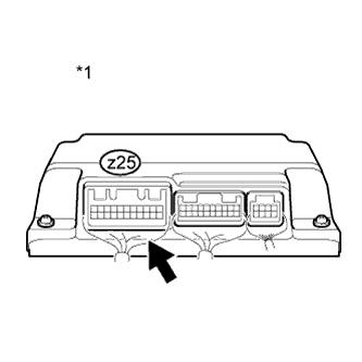
Text in Illustration *1 Battery Smart Unit Check the connections of the z25 connector of the battery smart unit.
OK The connectors are connected securely and there are no contact problems. -
Install the battery cover Click here.
-
Connect the cable to the negative (-) battery terminal.
NG
CONNECT SECURELY
OK
-
-
REPLACE BATTERY SMART UNIT
-
Replace the battery smart unit Click here.
NEXT
-
-
CLEAR DTC (HV)
-
Connect the intelligent tester to the DLC3.
-
Turn the power switch on (IG).
-
Enter the following menus: Powertrain / Hybrid Control / Trouble Codes.
-
Clear the DTCs and freeze frame data Click here.
-
Perform a road test to charge and discharge the HV battery assembly.
-
Disconnect the intelligent tester from the DLC3.
NEXT
-
-
RECONFIRM DTC OUTPUT (HV)
-
Connect the intelligent tester to the DLC3.
-
Turn the power switch on (IG).
-
Enter the following menus: Powertrain / Hybrid Control / Trouble Codes.
-
Read output DTCs Click here.
Result Result Proceed to Battery voltage sensor DTCs for this diagnostic procedure are not output A Battery voltage sensor DTCs for this diagnostic procedure are output B Tech Tips
Turning the power switch on (IG) with the service plug grip removed causes an interlock switch system DTC (P0A0D-350) to be set. Use the intelligent tester to clear the DTCs Click here.
-
Disconnect the intelligent tester to the DLC3.
B
REPLACE HV BATTERY ASSEMBLY Click here
A 
RETURNS TO NORMAL OPERATION
-