HYBRID BATTERY SYSTEM, Diagnostic DTC:P0AD3-123

| DTC Code | DTC Name |
|---|---|
| P0AD3-123 | Hybrid Battery Pack Cooling Fan 3 Control Circuit High |
DESCRIPTION
-
Refer to the Description for DTC P0A84-123 Click here.
| DTC No. | DTC Detection Condition | Trouble Area |
|---|---|---|
| P0AD3-123 | Voltage at battery cooling blower assembly (No. 2) (VM2) is out of the predetermined range in proportion to the target control voltage (1 trip detection). |
|
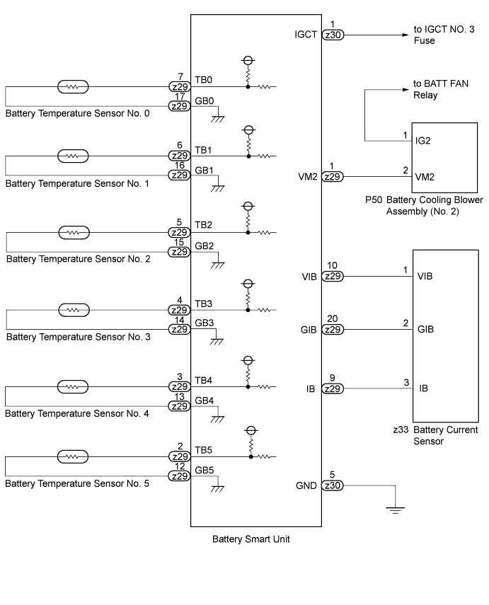
WIRING DIAGRAM
INSPECTION PROCEDURE
CAUTION:
-
Before inspecting the high-voltage system, take safety precautions to prevent electrical shocks, such as wearing insulated gloves and removing the service plug grip. After removing the service plug grip, put it in your pocket to prevent other technicians from accidentally reconnecting it while you are working on the high-voltage system.
-
After disconnecting the service plug grip, wait for at least 10 minutes before touching any of the high-voltage connectors or terminals.
Tech Tips
At least 10 minutes is required to discharge the high-voltage capacitor inside the inverter with converter assembly.
Note
After the power switch is turned off, the display and navigation module display (HDD navigation system) records various types of memory and settings. As a result, after turning the power switch off, make sure to wait for the time specified in the following table before disconnecting the cable from the negative (-) battery terminal.
| Specification | Waiting Time |
|---|---|
| w/o Telematics transceiver | 60 sec. |
| w/ Telematics transceiver | 120 sec. |
PROCEDURE
-
CHECK DTC OUTPUT (DTC P0AFC-123 IS OUTPUT)
-
Connect the intelligent tester to the DLC3.
-
Turn the power switch on (IG).
-
Enter the following menus: Powertrain / Hybrid Control / Trouble Codes.
-
Read output DTCs Click here.
Result Result Proceed to P0AFC-123 is not output. A P0AFC-123 is also output. B -
Disconnect the intelligent tester from the DLC3.
B 
GO TO DTC CHART
A 
-
-
CHECK HARNESS AND CONNECTOR (VM2 VOLTAGE)
CAUTION:
Be sure to wear insulated gloves and protective goggles.
-
Disconnect the cable from the negative (-) battery terminal.
-
Check that the service plug grip is not installed.
Note
After removing the service plug grip, do not turn the power switch on (READY), unless instructed by the repair manual because this may cause a malfunction.
-
Remove the battery cover Click here.
-
Remove the battery smart unit.
Tech Tips
Do not disconnect the battery smart unit connector.
-
Connect the cable to the negative (-) battery terminal.
-
Connect the intelligent tester to the DLC3.
-
Turn the power switch on (IG) and the intelligent tester on.
-
Enter the following menus: Powertrain / Hybrid Control / Active Test / Driving the Battery Cooling Fan.
-
Select each air volume mode (1 to 6) in the "Driving the Battery Cooling Fan" active test to operate the battery cooling blower assembly.
-
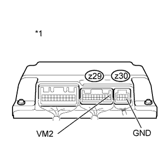
Text in Illustration *1 Component with harness connected
(Battery Smart Unit)
Measure the voltage according to the value(s) in the table below while the cooling fan is operating.
Standard Voltage Tester Connection Switch Condition Specified Condition z29-1(VM2) - z30-5(GND) Power switch on (IG) 5 V or less Note
If the power switch is turned on (IG) with the service plug grip removed, DTC P0A0D-350 for the interlock switch system will be stored. If this DTC is output, clear the DTC using the intelligent tester Click here.
Tech Tips
Compare the values in each air volume mode (1 to 6).
-
Install the battery smart unit Click here.
-
Install the battery cover.
-
Connect the cable to the negative (-) battery terminal.
NG 
OK
-
-
CHECK HV BATTERY ASSEMBLY
CAUTION:
Be sure to wear insulated gloves and protective goggles.
-
Disconnect the cable from the negative (-) battery terminal.
-
Check that the service plug grip is not installed.
Note
After removing the service plug grip, do not turn the power switch on (READY), unless instructed by the repair manual because this may cause a malfunction.
-
Remove the battery cover Click here.
-
Remove the battery smart unit.
Tech Tips
Disconnect the z29 and z30 connectors from the battery smart unit.
-
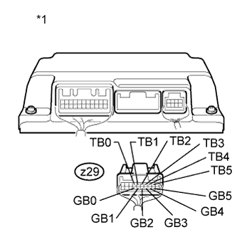
Text in Illustration *1 Rear view of wire harness connector
(to Battery Smart Unit)
Measure the resistance according to the conditions and value(s) in the tables below.
Tester Connection Battery Temperature Sensor No. z29-7 (TB0) - z29-17 (GB0) 0 z29-6 (TB1) - z29-16 (GB1) 1 z29-5 (TB2) - z29-15 (GB2) 2 z29-4 (TB3) - z29-14 (GB3) 3 z29-3 (TB4) - z29-13 (GB4) 4 z29-2 (TB5) - z29-12 (GB5) 5 Standard Resistance Thermistor Temperature Switch Condition Specified Condition 0°C (32°F) Power switch off 27.3 to 28.4 kΩ 25°C (77°F) Power switch off 9.9 to 10.1 kΩ 40°C (104°F) Power switch off 5.72 to 5.90 kΩ -
Text in Illustration *1 Rear view of wire harness connector
(to Battery Smart Unit)
Measure the resistance according to the conditions and value(s) in the tables below.
Standard Resistance Tester Connection Switch Condition Standard Resistance z29-7 (TB0) - z30-1(IGCT) Power switch off 10 kΩ or more z29-6 (TB1) - z30-1(IGCT) Power switch off 10 kΩ or more z29-5 (TB2) - z30-1(IGCT) Power switch off 10 kΩ or more z29-4 (TB3) - z30-1(IGCT) Power switch off 10 kΩ or more z29-3 (TB4) - z30-1(IGCT) Power switch off 10 kΩ or more z29-2 (TB5) - z30-1(IGCT) Power switch off 10 kΩ or more z29-17 (GB0) - z30-1(IGCT) Power switch off 10 kΩ or more z29-16 (GB1) - z30-1(IGCT) Power switch off 10 kΩ or more z29-15 (GB2) - z30-1(IGCT) Power switch off 10 kΩ or more z29-14 (GB3) - z30-1(IGCT) Power switch off 10 kΩ or more z29-13 (GB4) - z30-1(IGCT) Power switch off 10 kΩ or more z29-12 (GB5) - z30-1(IGCT) Power switch off 10 kΩ or more -
Install the battery smart unit Click here.
-
Install the battery cover.
-
Connect the cable to the negative (-) battery terminal.
NG
OK
-
-
CHECK HYBRID BATTERY JUNCTION BLOCK ASSEMBLY (CURRENT SENSOR)
CAUTION:
Be sure to wear insulated gloves and protective goggles.
-
Disconnect the cable from the negative (-) battery terminal.
-
Check that the service plug grip is not installed.
Note
After removing the service plug grip, do not turn the power switch on (READY), unless instructed by the repair manual because this may cause a malfunction.
-
Remove the battery cover Click here.
-
Remove the battery smart unit.
Tech Tips
Do not disconnect the battery smart unit connector.
-
Connect the cable to the negative (-) battery terminal.
-
Turn the power switch on (IG).
-
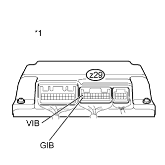
Text in Illustration *1 Component with harness connected
(Battery Smart Unit)
Measure the voltage according to the value(s) in the table below.
Standard Voltage Tester Connection Switch Condition Specified Condition z29-10 (VIB) - z29-20 (GIB) Power switch on (IG) 4.6 to 5.4 V Note
Turning the power switch on (IG) with the service plug grip removed causes an interlock switch system DTC (P0A0D-350) to be set. Use the intelligent tester to clear the DTCs Click here.
-
Install the battery smart unit Click here.
-
Install the battery cover.
NG
OK 
REPLACE BATTERY SMART UNIT Click here
-
-
CHECK HYBRID BATTERY JUNCTION BLOCK ASSEMBLY
CAUTION:
Be sure to wear insulated gloves and protective goggles.
-
Disconnect the cable from the negative (-) battery terminal.
-
Check that the service plug grip is not installed.
Note
After removing the service plug grip, do not turn the power switch on (READY), unless instructed by the repair manual because this may cause a malfunction.
-
Remove the battery cover Click here.
-
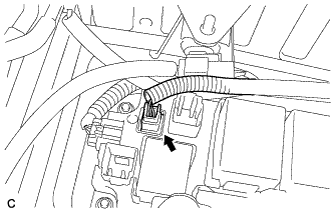
Disconnect the z33 battery current sensor connector from the hybrid battery junction block assembly.
-
Connect the cable to the negative (-) battery terminal.
-
Turn the power switch on (IG).
-
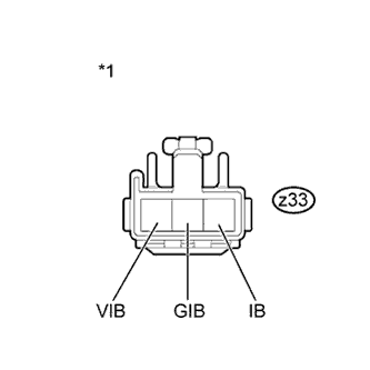
Text in Illustration *1 Front view of wire harness connector
(to Hybrid Battery Junction Block Assembly)
Measure the voltage according to the value(s) in the table below.
Standard Voltage Tester Connection Switch Condition Specified Condition z33-1 (VIB) - z33-2 (GIB) Power switch on (IG) 4.6 to 5.4 V Note
Turning the power switch on (IG) with the HV relay assembly (battery current sensor) connector disconnected causes DTC P0AC2-123 to be set. Use the intelligent tester to clear the DTCs Click here.
-
Connect the z33 battery current sensor connector to the hybrid battery junction block assembly.
-
Install the battery cover Click here.
NG
OK
REPLACE HYBRID BATTERY JUNCTION BLOCK ASSEMBLY Click here
-
-
CHECK BATTERY COOLING BLOWER ASSEMBLY (NO. 2)
CAUTION:
Be sure to wear insulated gloves and protective goggles.
-
Disconnect the cable from the negative (-) battery terminal.
-
Check that the service plug grip is not installed.
Note
After removing the service plug grip, do not turn the power switch on (READY), unless instructed by the repair manual because this may cause a malfunction.
-
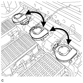
Remove the battery cover and replace the battery cooling blower assembly (No. 2) with another battery cooling blower assembly Click here.
-
Install the battery cover Click here.
-
Connect the cable to the negative (-) battery terminal.
-
Connect the intelligent tester to the DLC3.
-
Turn the power switch on (IG).
-
Enter the following menus: Powertrain / Hybrid Control / Active Test / Driving the Battery Cooling Fan.
Tech Tips
When the power switch is turned on (IG) for the first time after reconnecting the battery, the battery cooling fans operate as an initial check. Therefore, even before the active test is performed, the malfunction may be reproduced as a result of the initial check.
-
Check if the blower assembly malfunctions in a different location while operating the cooling fans (battery cooling blower assemblies).
Result Result Proceed to The malfunction is reproduced in the same battery cooling blower. A The malfunction is reproduced in another battery cooling blower. B -
Disconnect the intelligent tester from the DLC3.
-
Return the battery cooling blower assemblies to their original positions.
B
REPLACE BATTERY COOLING BLOWER ASSEMBLY (NO. 2) Click here
A
-
-
CHECK HARNESS AND CONNECTOR (BATTERY SMART UNIT - BATTERY COOLING BLOWER ASSEMBLY (NO. 2))
CAUTION:
Be sure to wear insulated gloves and protective goggles.
-
Disconnect the cable from the negative (-) battery terminal.
-
Check that the service plug grip is not installed.
Note
After removing the service plug grip, do not turn the power switch on (READY), unless instructed by the repair manual because this may cause a malfunction.
-
Remove the battery cover Click here.
-
Remove the battery smart unit.
Tech Tips
Disconnect only the z29 connector of the battery smart unit.
-
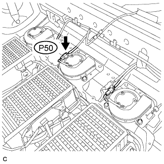
Disconnect the P50 connector from the battery cooling blower (No. 2).
-
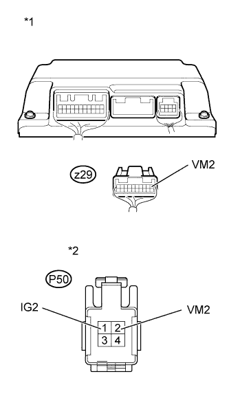
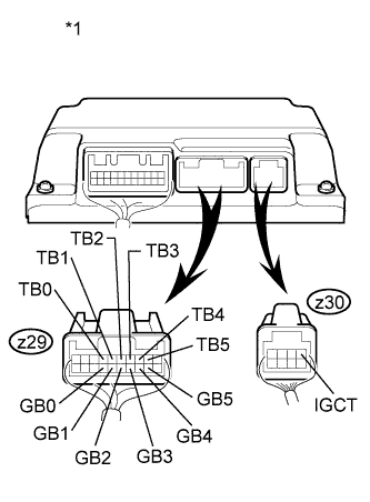
Text in Illustration *1 Rear view of wire harness connector
(to Battery Smart Unit)
*2 Front view of wire harness connector
(to Battery Cooling Blower Assembly (No. 2))
Measure the resistance according to the value(s) in the table below.
Standard Resistance (Check for Open) Tester Connection Switch Condition Specified Condition P50-2(VM2) - z29-1(VM2) Power switch off Below 1 Ω Standard Resistance (Check for Short) Tester Connection Switch Condition Specified Condition P50-2(VM2) or z29-1(VM2) - P50-1(IG2) Power switch off 10 kΩ or higher -
Connect the P50 connector to the battery cooling blower (No. 2).
-
Install the battery smart unit Click here.
-
Install the battery cover.
-
Connect the cable to the negative (-) battery terminal.
NG
REPAIR OR REPLACE HARNESS OR CONNECTOR
OK
REPLACE BATTERY SMART UNIT Click here
-
-
CHECK HARNESS AND CONNECTOR (BATTERY SMART UNIT - HYBRID BATTERY JUNCTION BLOCK ASSEMBLY)
CAUTION:
Be sure to wear insulated gloves and protective goggles.
-
Disconnect the cable from the negative (-) battery terminal.
-
Check that the service plug grip is not installed.
Note
After removing the service plug grip, do not turn the power switch on (READY), unless instructed by the repair manual because this may cause a malfunction.
-
Remove the battery cover Click here.
-
Remove the battery smart unit.
Tech Tips
Disconnect only the z29 connector of the battery smart unit.
-
Disconnect the z33 battery current sensor connector from the hybrid battery junction block assembly .
-
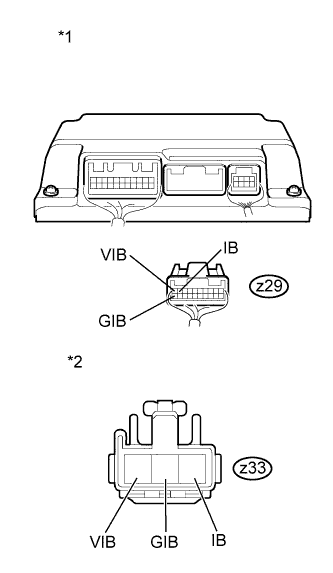
Text in Illustration *1 Rear view of wire harness connector
(to Battery Smart Unit)
*2 Front view of wire harness connector
(to Hybrid Battery Junction Block Assembly)
Measure the resistance according to the value(s) in the table below.
Standard Resistance (Check for Open) Tester Connection Switch Condition Specified Condition z29-9 (IB) - z33-3 (IB) Power switch off Below 1 Ω z29-20 (GIB) - z33-2 (GIB) Power switch off Below 1 Ω z29-10 (VIB) - z33-1 (VIB) Power switch off Below 1 Ω Standard Resistance (Check for Short) Tester Connection Switch Condition Specified Condition z29-9 (IB) or z33-3 (IB) - Body ground and other terminals Power switch off 10 kΩ or higher z29-20 (GIB) or z33-2 (GIB) - Body ground and other terminals Power switch off 10 kΩ or higher z29-10 (VIB) or z33-1 (VIB) - Body ground and other terminals Power switch off 10 kΩ or higher -
Connect the z33 battery current sensor connector to the hybrid battery junction block assembly.
-
Install the battery smart unit Click here.
-
Install the battery cover.
-
Connect the cable to the negative (-) battery terminal.
NG
REPAIR OR REPLACE HARNESS OR CONNECTOR
OK
REPLACE BATTERY SMART UNIT Click here
-
-
CHECK HARNESS AND CONNECTOR (BATTERY TEMPERATURE SENSOR)
CAUTION:
Be sure to wear insulated gloves and protective goggles.
-
Disconnect the cable from the negative (-) battery terminal.
-
Check that the service plug grip is not installed.
Note
After removing the service plug grip, do not turn the power switch on (READY), unless instructed by the repair manual because this may cause a malfunction.
-
Remove the battery cover Click here.
-
Remove the group of HV battery modules which includes the malfunctioning battery temperature sensor.
-
Turn the group of HV battery modules over. Check the wire harness and connectors of the battery temperature sensor for abnormalities by sight and touch.
Specified Condition There are no open or short circuits in the wire harness and connectors. There are no short circuits to other wire harnesses.
NG
REPAIR HARNESS OR CONNECTOR
OK
REPLACE HV BATTERY ASSEMBLY Click here
-