HYBRID BATTERY SYSTEM, Diagnostic DTC:P0A95-123

| DTC Code | DTC Name |
|---|---|
| P0A95-123 | High Voltage Fuse |
DESCRIPTION
| DTC No. | DTC Detection Condition | Trouble Area |
|---|---|---|
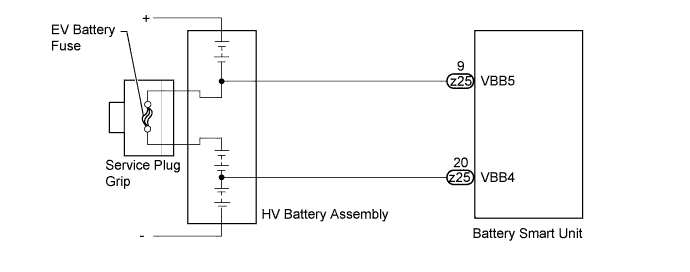
| P0A95-123 | Voltage between VBB4 and VBB5 terminals is below the standard despite the interlock switch being engaged (1 trip detection) |
|
WIRING DIAGRAM
INSPECTION PROCEDURE
CAUTION:
-
Before inspecting the high-voltage system, take safety precautions to prevent electrical shocks, such as wearing insulated gloves and removing the service plug grip. After removing the service plug grip, put it in your pocket to prevent other technicians from accidentally reconnecting it while you are working on the high-voltage system.
-
After disconnecting the service plug grip, wait for at least 10 minutes before touching any of the high-voltage connectors or terminals.
Tech Tips
At least 10 minutes is required to discharge the high-voltage capacitor inside the inverter with converter assembly.
Note
After the power switch is turned off, the display and navigation module display (HDD navigation system) records various types of memory and settings. As a result, after turning the power switch off, make sure to wait for the time specified in the following table before disconnecting the cable from the negative (-) battery terminal.
| Specification | Waiting Time |
|---|---|
| w/o Telematics transceiver | 60 sec. |
| w/ Telematics transceiver | 120 sec. |
PROCEDURE
-
CHECK DTC OUTPUT (DTC P0AFC-123 IS OUTPUT)
-
Connect the intelligent tester to the DLC3.
-
Turn the power switch on (IG).
-
Enter the following menus: Powertrain / Hybrid Control / Trouble Codes.
-
Read output DTCs Click here.
Result Result Proceed to P0AFC-123 is not output. A P0AFC-123 is also output. B -
Disconnect the intelligent tester from the DLC3.
B 
GO TO DTC CHART
A 
-
-
CHECK SERVICE PLUG GRIP
-
Turn the power switch off.
-
Check that the service plug grip is not installed.
Note
After removing the service plug grip, do not turn the power switch on (READY), unless instructed by the repair manual because this may cause a malfunction.
-
Measure the resistance according to the value(s) in the table below.
Standard Resistance Tester Connection Standard Resistance Service plug grip Below 1 Ω
NG
REPLACE SERVICE PLUG GRIP Click here
OK
-
-
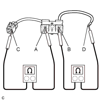
CHECK ELECTRIC VEHICLE BATTERY PLUG ASSEMBLY
CAUTION:
Be sure to wear insulated gloves and protective goggles.
-
Check that the service plug grip is not installed.
Note
After removing the service plug grip, do not turn the power switch on (READY), unless instructed by the repair manual because this may cause a malfunction.
-
Remove the battery cover Click here.
-
Remove the electric vehicle battery plug assembly.
-
Measure the resistance according to the value(s) in the table below.
Standard Resistance Tester Connection Specified Condition A - C Below 1 Ω B - D Below 1 Ω -
Install the electric vehicle battery plug assembly Click here.
-
Install the battery cover.
NG
REPLACE ELECTRIC VEHICLE BATTERY PLUG ASSEMBLY Click here
OK
-
-
CHECK NO. 2 HV BATTERY PACK CABLE
CAUTION:
Be sure to wear insulated gloves and protective goggles.
-
Check that the service plug grip is not installed.
Note
After removing the service plug grip, do not turn the power switch on (READY), unless instructed by the repair manual because this may cause a malfunction.
-
Remove the battery cover Click here.
-
Remove the electric vehicle battery plug assembly.
-
Remove the No. 2 HV battery pack cable.
-
Measure the resistance between the No. 2 HV battery pack cable terminals.
Standard Resistance Tester Connection Standard Resistance No. 2 HV battery pack cable Below 1 Ω -
Install the No. 2 HV battery pack cable Click here.
-
Install the electric vehicle battery plug assembly.
-
Install the battery cover.
NG
REPLACE NO. 2 HV BATTERY PACK CABLE Click here
OK 
REPLACE HV BATTERY ASSEMBLY Click here
-