AUDIO AND VISUAL SYSTEM (w/o Navigation System), Diagnostic DTC:01-DC

| DTC Code | DTC Name |
|---|---|
| 01-DC | Transmission Error |
DESCRIPTION
| DTC No. | DTC Detection Condition | Trouble Area |
|---|---|---|
| 01-DC *1 |
Transmission to component shown by sub-code failed (Detecting this DTC does not always mean actual failure). | If the same sub-code is stored in other components, check power source circuit and communication system of all components shown by sub-code |
Tech Tips
*1: If the power switch is turned off after idling for 60 seconds, this DTC may be stored when the engine is started again.
Note
-
Before starting troubleshooting, be sure to clear the DTCs stored due to the reason described in the HINT above. Then, check for DTCs and troubleshoot according to the output DTCs.
-
The radio receiver assembly is the master unit.
-
Be sure to clear and recheck for the DTCs after the inspection is completed to confirm that no DTCs are output.
INSPECTION PROCEDURE
Note
Be sure to read Description before performing the following procedure.
PROCEDURE
-
CHECK FOR DTC OF OTHER COMPONENTS
-
Check if the component shown by the sub-code is displayed in the check result of the other components.
-
Check if "01-DC" is output for the other components.
-
If "01-DC" is output for any other components, check if the same physical address is displayed.
Result Result Proceed to "01-DC" is output and the same physical address is displayed A "01-DC" is not output or the same physical address is not displayed B Tech Tips
For the list of the components shown by sub-codes, refer to the table in step 2.
-
B 
CLEAR DTC Click here
A 
-
-
IDENTIFY COMPONENT WHICH HAS STORED THIS CODE
-
Enter diagnostic mode.
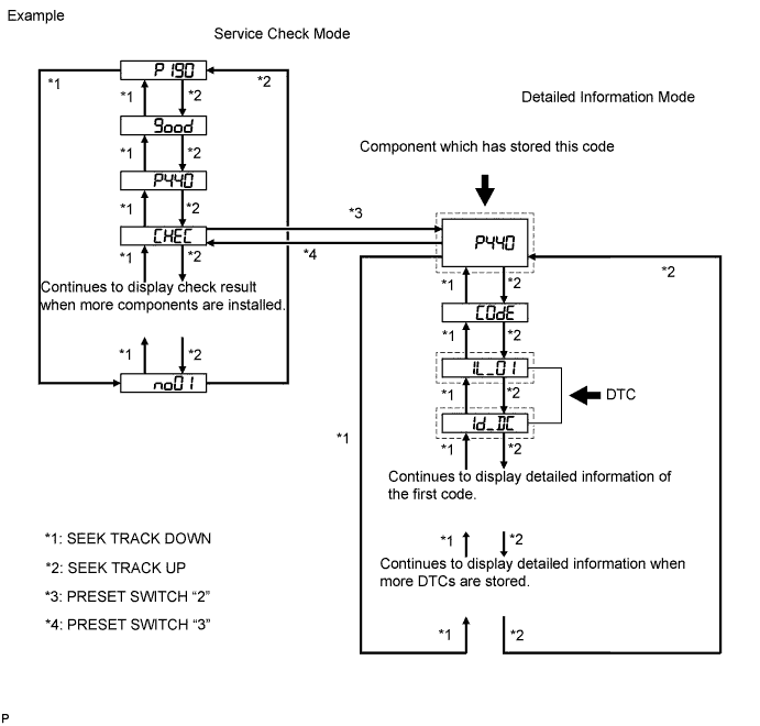
-
Press preset switch "2" to change the mode to "Detailed Information Mode".
-
Identify the component which has stored this code.
Component Table Component Physical Address Stereo component amplifier assembly 440 Radio receiver assembly 190 Accessory meter assembly 1D4 Multi-media interface ECU 388 Air conditioning control panel 1C4 Tech Tips
-
"P440" set by the stereo component amplifier assembly is shown in the preceding illustration as an example.
-
For details of the DTC display, refer to DTC Check/Clear Click here.
-
NEXT
-
-
CHECK COMPONENT WHICH HAS STORED THIS CODE
-
Select the component which has stored this code.
Component Table Component Proceed to Stereo component amplifier assembly Stereo component amplifier communication error Click here
Radio receiver assembly Radio receiver communication error Click here
Accessory meter assembly Accessory meter communication error Click here
Multi-media interface ECU Multi-media interface ECU communication error Click here
Air conditioning control panel Air conditioning control panel communication error Click here
NEXT 
END
-
-
CLEAR DTC
-
Clear the DTCs Click here.
Tech Tips
If "01-DC" is output for only one component, this may not indicate a malfunction.
NEXT
-
-
RECHECK FOR DTC
-
Recheck for DTCs and check if the same trouble occurs again.
OK Malfunction disappears.
NG
CHECK COMPONENT WHICH HAS STORED THIS CODE Click here
OK
END
-
-
CHECK COMPONENT WHICH HAS STORED THIS CODE
-
Select the component which has stored this code.
Component Table Component Proceed to Stereo component amplifier assembly Stereo component amplifier communication error Click here
Radio receiver assembly Radio receiver communication error Click here
Accessory meter assembly Accessory meter communication error Click here
Multi-media interface ECU Multi-media interface ECU communication error Click here
Air conditioning control panel Air conditioning control panel communication error Click here
NEXT
END
-