AUDIO AND VISUAL SYSTEM (w/ Navigation System) Multi-media Interface ECU Power Source Circuit
DESCRIPTION
This circuit provides power to the multi-media interface ECU.
WIRING DIAGRAM
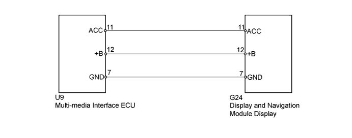
INSPECTION PROCEDURE
Note
When replacing the display and navigation module display, perform vehicle contract setting (w/ G-BOOK system Click here)
PROCEDURE
-
INSPECT MULTI-MEDIA INTERFACE ECU
-
Disconnect the multi-media interface ECU connector.
-
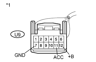
Text in Illustration *1 Front view of wire harness connector
(to Multi-media Interface ECU)
Measure the voltage according to the value(s) in the table below.
Standard Voltage Tester Connection Condition Specified Condition U9-12 (+B) - U9-7 (GND) Always 11 to 14 V U9-11 (ACC) - U9-7 (GND) Power switch on (ACC) 11 to 14 V
NG 
CHECK HARNESS AND CONNECTOR Click here
OK 
PROCEED TO NEXT SUSPECTED AREA SHOWN IN PROBLEM SYMPTOMS TABLE Click here
-
-
CHECK HARNESS AND CONNECTOR
-
Disconnect the display and navigation module display connector.
-
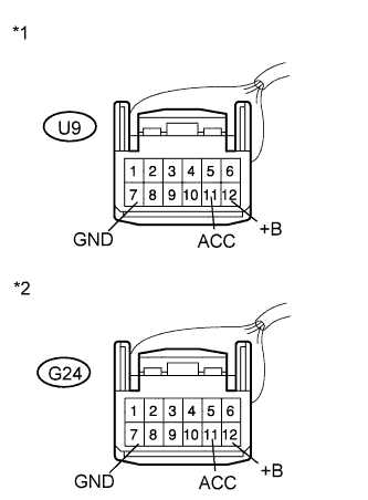
Text in Illustration *1 Front view of wire harness connector
(to Multi-media Interface ECU)
*2 Front view of wire harness connector
(to Display and Navigation Module Display)
Measure the resistance according to the value(s) in the table below.
Standard Resistance Tester Connection Condition Specified Condition U9-11 (ACC) - G24-11 (ACC) Always Below 1 Ω U9-12 (+B) - G24-12 (+B) Always Below 1 Ω U9-7 (GND) - G24-7 (GND) Always Below 1 Ω U9-11 (ACC) - Body ground Always 10 kΩ or higher U9-12 (+B) - Body ground Always 10 kΩ or higher U9-7 (GND) - Body ground Always 10 kΩ or higher
NG 
REPAIR OR REPLACE HARNESS OR CONNECTOR
OK
REPLACE DISPLAY AND NAVIGATION MODULE DISPLAY Click here
-