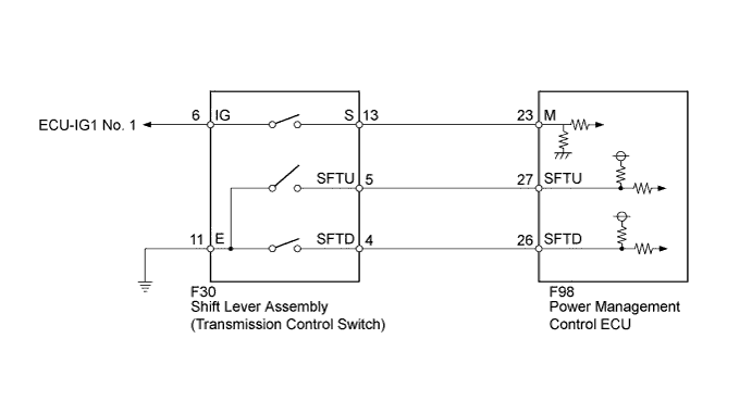
HYBRID CONTROL SYSTEM Transmission Control Switch Circuit
DESCRIPTION
When the shift lever is in the S position, different ranges can be chosen using the floor shift sequential gate.
INSPECTION PROCEDURE
PROCEDURE
-
READ VALUE USING INTELLIGENT TESTER (SPORTS MODE)
-
Connect the intelligent tester to the DLC3.
-
Turn the power switch on (IG).
-
Enter the following menus: Powertrain / Hybrid Control / Data List / Sports Mode.
-
Read the Data List.
Result Tester Display Measurement Item/Range Normal Condition Sports Mode Sports shift signal
ON or OFF
Shift lever in S position: ON
Shift lever not in S position: OFF
NG 
CHECK HARNESS AND CONNECTOR (POWER SOURCE CIRCUIT) Click here
OK 
-
-
READ VALUE USING INTELLIGENT TESTER (SPORTS SHIFT UP SIGNAL/SPORTS SHIFT DOWN SIGNAL)
-
Enter the following menus: Powertrain / Hybrid Control / Data List / Sports Shift Up Signal/Sports Shift Down Signal.
-
Read the Data List.
Result Tester Display Measurement Item/Range Normal Condition Sports Shift Up Signal Sports shift UP signal
ON or OFF
Shift lever in positive (+): ON
Shift lever not in positive (+): OFF
Sports Shift Down Signal Sports shift DOWN signal
ON or OFF
Shift lever in negative (-): ON
Shift lever not in negative (-): OFF
NG
CHECK SHIFT LEVER ASSEMBLY (TRANSMISSION CONTROL SWITCH) Click here
OK
-
-
CHECK FOR INTERMITTENT PROBLEMS
-
Check for intermittent problems.
-
Move the shift lever to S and jiggle the harness and connector.
-
With the shift lever held toward "+" and then "-", jiggle the harness and connector.
Result Result Proceed to Malfunction occurs A Malfunction does not occur for LHD B for RHD C -
B 
REPLACE POWER MANAGEMENT CONTROL ECU (for LHD) Click here
C
REPLACE POWER MANAGEMENT CONTROL ECU (for RHD) Click here
A 
REPAIR OR REPLACE MALFUNCTIONING PARTS, COMPONENT AND AREA
-
-
CHECK SHIFT LEVER ASSEMBLY (TRANSMISSION CONTROL SWITCH)
-
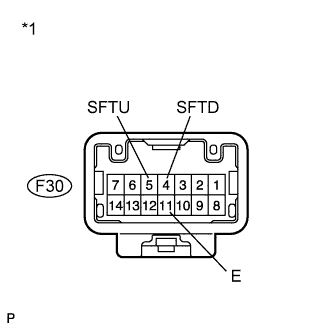
Text in Illustration *1 Component without harness connected
(Transmission Control Switch)
Disconnect connector F30 from the transmission control switch.
-
Measure the resistance according to the value(s) in the table below.
Standard Resistance Tester Connection Condition Specified Condition F30-5 (SFTU) - F30-11 (E) Shift lever in S and held toward + Below 1 Ω F30-5 (SFTU) - F30-11 (E)
F30-4 (SFTD) - F30-11 (E)
Shift lever in S and not held toward + or - 10 kΩ or higher F30-4 (SFTD) - F30-11 (E) Shift lever in S and held toward - Below 1 Ω -
Connect the transmission control switch connector.
NG
REPLACE SHIFT LEVER ASSEMBLY Click here
OK
-
-
CHECK HARNESS AND CONNECTOR (TRANSMISSION CONTROL SWITCH - POWER MANAGEMENT CONTROL ECU)
-
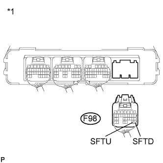
Text in Illustration *1 Rear view of wire harness connector
(to Power Management Control ECU)
Disconnect connector F98 from the power management control ECU.
-
Measure the resistance according to the value(s) in the table below.
Standard Resistance Tester Connection Condition Specified Condition F98-27 (SFTU) - Body ground Shift lever in positive (+) Below 1 Ω F98-27 (SFTU) - Body ground
F98-26 (SFTD) - Body ground
Shift lever in S 10 kΩ or higher F98-26 (SFTD) - Body ground Shift lever in negative (-) Below 1 Ω Result Result Proceed to NG A OK (for LHD) B OK (for RHD) C -
Connect the power management control ECU connector.
B
REPLACE POWER MANAGEMENT CONTROL ECU (for LHD) Click here
C
REPLACE POWER MANAGEMENT CONTROL ECU (for RHD) Click here
A
REPAIR OR REPLACE HARNESS OR CONNECTOR
-
-
CHECK HARNESS AND CONNECTOR (POWER SOURCE CIRCUIT)
-
Disconnect connector F30 from the transmission control switch.
-
Turn the power switch on (IG).
-
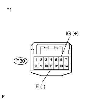
Text in Illustration *1 Front view of wire harness connector
(to Transmission Control Switch)
Measure the voltage according to the value(s) in the table below.
Standard Voltage Tester Connection Switch Condition Specified Condition F30-6 (IG) - F30-11 (E) Power switch on (IG) 11 to 14 V -
Turn the power switch off.
-
Connect the transmission control switch connector.
NG
CHECK POWER SOURCE CIRCUIT
OK
-
-
CHECK SHIFT LEVER ASSEMBLY (TRANSMISSION CONTROL SWITCH)
-
Disconnect connector F30 from the transmission control switch.
-
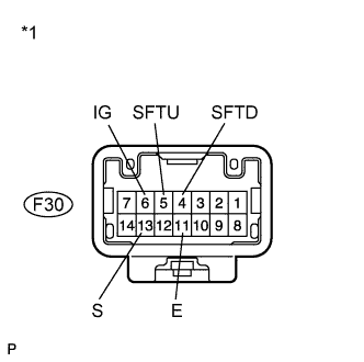
Text in Illustration *1 Component without harness connected
(Transmission Control Switch)
Measure the resistance according to the value(s) in the table below.
Standard Resistance Tester Connection Condition Specified Condition F30-6 (IG) - F30-13 (S) Shift lever not in S 10 kΩ or higher F30-6 (IG) - F30-13 (S) Shift lever in S Below 1 Ω F30-5 (SFTU) - F30-11 (E) Shift lever in positive (+) Below 1 Ω F30-5 (SFTU) - F30-11 (E)
F30-4 (SFTD) - F30-11 (E)
Shift lever not in S 10 kΩ or higher F30-4 (SFTD) - F30-11 (E) Shift lever in negative (-) Below 1 Ω -
Connect the transmission control switch connector.
NG
REPLACE SHIFT LEVER ASSEMBLY Click here
OK
-
-
CHECK HARNESS AND CONNECTOR (TRANSMISSION CONTROL SWITCH - POWER MANAGEMENT CONTROL ECU)
-
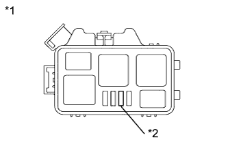
Text in Illustration *1 Engine Room Relay Block No. 2 *2 IGCT No. 3 Fuse Remove the IGCT No. 3 fuse from the engine room relay block No. 2.
-
Text in Illustration *1 Engine Room Junction Block Assembly *2 AM2 Fuse Remove the AM2 fuse from the engine room junction block assembly.
-
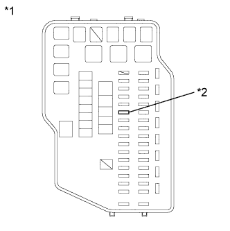
Text in Illustration *1 Instrument Panel Junction Block Assembly *2 ECU IG2 Fuse Remove the ECU IG2 fuse from the instrument panel junction block assembly.
-
Disconnect all the connectors from the power management control ECU.
-
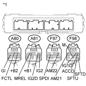
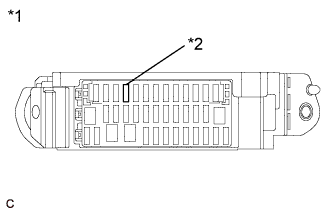
Text in Illustration *1 Power Management Control ECU Measure the resistance according to the value(s) in the table below.
Standard Resistance Tester Connection Switch Condition Specified Condition F98-23 (M) - A80-2 (+B2) Power switch off 10 kΩ or higher F98-23 (M) - A81-5 (+B1) Power switch off 10 kΩ or higher F98-23 (M) - F97-1 (AM22) Power switch off 10 kΩ or higher F98-23 (M) - F98-7 (AM21) Power switch off 10 kΩ or higher F98-23 (M) - A81-6 (MREL) Power switch off 10 kΩ or higher F98-23 (M) - A81-1 (IG2) Power switch off 10 kΩ or higher F98-23 (M) - F98-1 (ACCD) Power switch off 10 kΩ or higher F98-23 (M) - F98-2 (IG1D) Power switch off 10 kΩ or higher F98-23 (M) - A81-2 (IG2D) Power switch off 10 kΩ or higher F98-23 (M) - F97-14 (SPDI) Power switch off 10 kΩ or higher F98-23 (M) - A80-16 (GI) Power switch off 10 kΩ or higher F98-23 (M) - A80-4 (FCTL) Power switch off 10 kΩ or higher F98-27 (SFTU) - Body ground Shift lever in positive (+) Below 1 Ω F98-27 (SFTU) - Body ground
F98-26 (SFTD) - Body ground
Shift lever in S 10 kΩ or higher F98-26 (SFTD) - Body ground Shift lever in negative (-) Below 1 Ω -
Disconnect connector F30 from the transmission control switch.
-
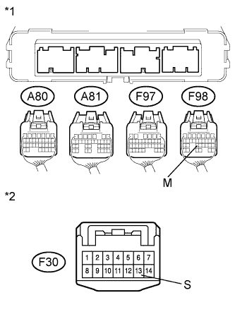
Text in Illustration *1 Rear view of wire harness connector
(to Power Management Control ECU)
*2 Front view of wire harness connector
(to Transmission Control Switch)
Measure the resistance according to the value(s) in the table below.
Standard Resistance Tester Connection Switch Condition Specified Condition F98-23 (M) - F30-13 (S) Power switch off Below 1 Ω Result Result Proceed to NG A OK (for LHD) B OK (for RHD) C -
Connect the transmission control switch connector.
-
Connect the power management control ECU connectors.
-
Install the ECU IG2 fuse to the instrument panel junction block assembly.
-
Install the AM2 fuse to the engine room junction block assembly.
-
Install the IGCT No. 3 fuse to the engine room relay block No. 2.
B
REPLACE POWER MANAGEMENT CONTROL ECU (for LHD) Click here
C
REPLACE POWER MANAGEMENT CONTROL ECU (for RHD) Click here
A
REPAIR OR REPLACE HARNESS OR CONNECTOR
-