HYBRID CONTROL SYSTEM, Diagnostic DTC:U0110-159, U0110-656, U0110-657

| DTC Code | DTC Name |
|---|---|
| U0110-159 | Lost Communication with Driver Motor Control Module |
| U0110-656 | Lost Communication with Driver Motor Control Module |
| U0110-657 | Lost Communication with Driver Motor Control Module |
DESCRIPTION
-
For a description of the inverter with converter assembly Click here.
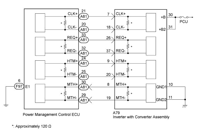
The inverter with converter assembly (MG ECU) controls MG2 based on commands from the power management control ECU (HV CPU). The inverter with converter assembly (MG ECU) monitors communication data and detects malfunctions.
| DTC No. | INF Code | DTC Detection Condition | Trouble Area |
|---|---|---|---|
| U0110 | 159 | Error in reception from inverter with converter assembly (MG ECU) via serial communication (out of communication standard) |
|
| U0110 | 656 | Error in reception from inverter with converter assembly (MG ECU) via serial communication (out of communication standard) | |
| U0110 | 657 | Error in reception from inverter with converter assembly (MG ECU) via serial communication (no reception) |
WIRING DIAGRAM
INSPECTION PROCEDURE
CAUTION:
-
Before inspecting the high-voltage system or disconnecting the low voltage connector of the inverter with converter assembly, take safety precautions such as wearing insulated gloves and removing the service plug grip to prevent electrical shocks. After removing the service plug grip, put it in your pocket to prevent other technicians from accidentally reconnecting it while you are working on the high-voltage system.
-
After disconnecting the service plug grip, wait for at least 10 minutes before touching any of the high-voltage connectors or terminals. After waiting for 10 minutes, check the voltage at the terminals in the inspection point in the inverter with converter assembly. The voltage should be 0 V before beginning work.
Note
If any of the DTCs U0110-159, U0110-656, and U0110-657 was set due to incomplete engagement of the connectors, and if the system returns to normal when the power switch is turned on (IG) after clearing the DTCs, DTC P324E-788 will be set. Proceed to troubleshooting without considering DTC P324E-788.
Tech Tips
Waiting for at least 10 minutes is required to discharge the high-voltage capacitor inside the inverter with converter assembly.
PROCEDURE
-
CHECK FUSE (PCU)
-
Remove the PCU fuse from the engine room relay block No. 2.
-
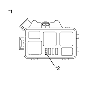
Text in Illustration *1 Engine Room Relay Block No. 2 *2 PCU Fuse Measure the resistance according to the value(s) in the table below.
Standard Resistance Tester Connection Switch Condition Specified Condition PCU fuse terminals Always Below 1 Ω -
Install the PCU fuse.
NG 
REPLACE FUSE (PCU) Click here
OK 
-
-
CLEAR DTC
-
Connect the intelligent tester to the DLC3.
-
Turn the power switch on (IG).
-
Enter the following menus: Powertrain / Hybrid Control / Trouble Codes.
-
Clear DTCs and freeze frame data.
NEXT
-
-
CHECK DTC OUTPUT (HV)
-
Connect the intelligent tester to the DLC3.
-
Turn the power switch on (IG).
-
Enter the following menus: Powertrain / Hybrid Control / Trouble Codes.
-
Check if DTCs are output.
Result Result Proceed to DTC U0110-159, 656 or 657 is output. A DTCU0110-159, 656 and 657 are not output. B -
Turn the power switch off.
B 
CHECK FOR INTERMITTENT PROBLEMS Click here
A
-
-
CHECK HARNESS AND CONNECTOR (INVERTER WITH CONVERTER ASSEMBLY POWER SOURCE CIRCUIT)
CAUTION:
Be sure to wear insulated gloves.
-
Check that the service plug grip is not installed.
Note
After removing the service plug grip, do not turn the power switch on (READY), unless instructed by the repair manual because this may cause a malfunction.
-
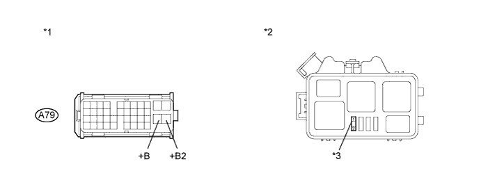
Disconnect the A79 connector from the inverter with converter assembly.
-
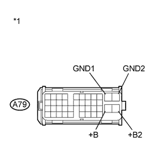
Text in Illustration *1 Front view of wire harness connector
(to Inverter with Converter Assembly)
Measure the resistance according to the value(s) in the table below.
Standard Resistance Tester Connection Switch Condition Specified Condition A79-10 (GND1) - Body ground Power switch off Below 1 Ω A79-11 (GND2) - Body ground Power switch off Below 1 Ω -
Turn the power switch on (IG).
-
Measure the voltage according to the value(s) in the table below.
Standard Voltage Tester Connection Switch Condition Specified Condition A79-30 (+B) - Body ground Power switch on (IG) 10 to 14 V A79-31 (+B2) - Body ground Power switch on (IG) 10 to 14 V Note
Turning the power switch on (IG) with the low voltage connector of the inverter with converter assembly disconnected causes other DTCs to be stored. Clear the DTCs after performing this inspection.
-
Turn the power switch off.
-
Connect the inverter with converter assembly connector.
NG
REPAIR OR REPLACE HARNESS OR CONNECTOR (INVERTER WITH CONVERTER ASSEMBLY POWER SOURCE CIRCUIT)
OK
-
-
CHECK POWER MANAGEMENT CONTROL ECU (CHECK WAVEFORM)
-
Turn the power switch on (IG).
-
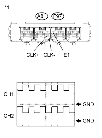
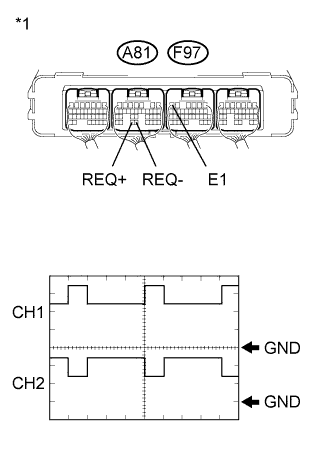
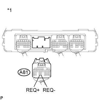
Text in Illustration *1 Component with harness connected
(Power Management Control ECU)
Connect an oscilloscope between the power management control ECU terminals specified in the following table, and measure the waveform.
Item Contents Tester Connection CH1: A81-21 (CLK+) - F97-6 (E1)
CH2: A81-20 (CLK-) - F97-6 (E1)
Equipment Setting 1V/DIV., 1μs/DIV. Condition Power switch on (IG) Tech Tips
-
Inspect with the connector connected.
-
If pulses are generated, the shape of the waveform can be assumed to be normal.
-
The shape of the waveform may vary according to communication conditions.
Result Result Proceed to The waveform appears as shown in the illustration. A The waveform differs from the one shown in the illustration. B -
-
Turn the power switch off.
B
CHECK HARNESS AND CONNECTOR (POWER MANAGEMENT CONTROL ECU - INVERTER WITH CONVERTER) Click here
A
-
-
CHECK POWER MANAGEMENT CONTROL ECU (CHECK WAVEFORM)
-
Turn the power switch on (IG).
-
Text in Illustration *1 Component with harness connected
(Power Management Control ECU)
Connect an oscilloscope between the power management control ECU terminals specified in the following table, and measure the waveform.
Item Contents Tester Connection CH1: A81-33 (REQ+) - F97-6 (E1)
CH2: A81-32 (REQ-) - F97-6 (E1)
Equipment Setting 1V/DIV., 1ms/DIV. Condition Power switch on (IG) Tech Tips
-
Inspect with the connector connected.
-
If pulses are generated, the shape of the waveform can be assumed to be normal.
-
The shape of the waveform may vary according to communication conditions.
Result Result Proceed to The waveform appears as shown in the illustration. A The waveform differs from the one shown in the illustration. B -
-
Turn the power switch off.
B
CHECK HARNESS AND CONNECTOR (POWER MANAGEMENT CONTROL ECU - INVERTER WITH CONVERTER) Click here
A
-
-
CHECK POWER MANAGEMENT CONTROL ECU (CHECK WAVEFORM)
-
Turn the power switch on (IG).
-
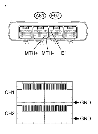
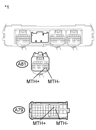
Text in Illustration *1 Component with harness connected
(Power Management Control ECU)
Connect an oscilloscope between the power management control ECU terminals specified in the following table, and measure the waveform.
Item Contents Tester Connection CH1: A81-30 (MTH+) - F97-6 (E1)
CH2: A81-29 (MTH-) - F97-6 (E1)
Equipment Setting 1V/DIV., 200μs/DIV. Condition Power switch on (IG) Tech Tips
-
Inspect with the connector connected.
-
If pulses are generated, the shape of the waveform can be assumed to be normal.
-
The shape of the waveform may vary according to communication conditions.
Result Result Proceed to The waveform appears as shown in the illustration. for LHD A for RHD B The waveform differs from the one shown in the illustration. C -
-
Turn the power switch off.
B
REPLACE POWER MANAGEMENT CONTROL ECU (for RHD) Click here
C
CHECK HARNESS AND CONNECTOR (POWER MANAGEMENT CONTROL ECU - INVERTER WITH CONVERTER) Click here
A 
REPLACE POWER MANAGEMENT CONTROL ECU (for LHD) Click here
-
-
CHECK HARNESS AND CONNECTOR (POWER MANAGEMENT CONTROL ECU - INVERTER WITH CONVERTER)
CAUTION:
Be sure to wear insulated gloves.
-
Check that the service plug grip is not installed.
Note
After removing the service plug grip, do not turn the power switch on (READY), unless instructed by the repair manual because this may cause a malfunction.
-
Disconnect the A81 connector from the power management control ECU.
-
Disconnect the A79 connector from the inverter with converter assembly.
-
Turn the power switch on (IG).
-
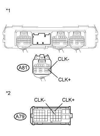
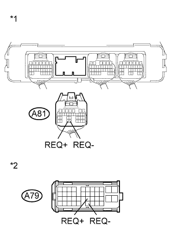
Text in Illustration *1 Rear view of wire harness connector
(to Power Management Control ECU)
*2 Front view of wire harness connector
(to Inverter with Converter Assembly)
Measure the voltage according to the value(s) in the table below.
Standard Voltage Tester Connection Switch Condition Specified Condition A81-21 (CLK+) - Body ground Power switch on (IG) Below 1 V A81-20 (CLK-) - Body ground Power switch on (IG) Below 1 V Note
Turning the power switch on (IG) with the power management control ECU connector and the low voltage connector of the inverter with converter assembly disconnected causes other DTCs to be stored. Clear the DTCs after performing this inspection.
-
Turn the power switch off.
-
Measure the resistance according to the value(s) in the table below.
Standard Resistance (Check for Open) Tester Connection Switch Condition Specified Condition A81-21 (CLK+) - A79-7 (CLK+) Power switch off Below 1 Ω A81-20 (CLK-) - A79-18 (CLK-) Power switch off Below 1 Ω Standard Resistance (Check for Short) Tester Connection Switch Condition Specified Condition A81-21 (CLK+) or A79-7 (CLK+) - Body ground and other terminals Power switch off 10 kΩ or higher A81-20 (CLK-) or A79-18 (CLK-) - Body ground and other terminals Power switch off 10 kΩ or higher -
Connect the inverter with converter assembly connector.
-
Connect the power management control ECU connector.
NG
REPAIR OR REPLACE HARNESS OR CONNECTOR
OK
-
-
CHECK INVERTER WITH CONVERTER ASSEMBLY
-
Disconnect the A81 connector from the power management control ECU.
-
Text in Illustration *1 Rear view of wire harness connector
(to Power Management Control ECU)
Measure the resistance according to the value(s) in the table below.
Standard Resistance Tester Connection Switch Condition Specified Condition A81-21 (CLK+) - A81-20 (CLK-) Power switch off 109 to 131 Ω Result Result Proceed to OK (for LHD) A OK (for RHD) B NG C -
Connect the power management control ECU connector.
B
REPLACE POWER MANAGEMENT CONTROL ECU (for RHD) Click here
C
REPLACE INVERTER WITH CONVERTER ASSEMBLY Click here
A
REPLACE POWER MANAGEMENT CONTROL ECU (for LHD) Click here
-
-
CHECK HARNESS AND CONNECTOR (POWER MANAGEMENT CONTROL ECU - INVERTER WITH CONVERTER)
CAUTION:
Be sure to wear insulated gloves.
-
Check that the service plug grip is not installed.
Note
After removing the service plug grip, do not turn the power switch on (READY), unless instructed by the repair manual because this may cause a malfunction.
-
Disconnect the A81 connector from the power management control ECU.
-
Disconnect the A79 connector from the inverter with converter assembly.
-
Turn the power switch on (IG).
-
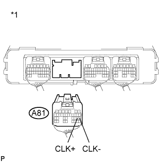
Text in Illustration *1 Rear view of wire harness connector
(to Power Management Control ECU)
*2 Front view of wire harness connector
(to Inverter with Converter Assembly)
Measure the voltage according to the value(s) in the table below.
Standard Voltage Tester Connection Switch Condition Specified Condition A81-33 (REQ+) - Body ground Power switch on (IG) Below 1 V A81-32 (REQ-) - Body ground Power switch on (IG) Below 1 V Note
Turning the power switch on (IG) with the power management control ECU connector and the low voltage connector of the inverter with converter assembly disconnected causes other DTCs to be stored. Clear the DTCs after performing this inspection.
-
Turn the power switch off.
-
Measure the resistance according to the value(s) in the table below.
Standard Resistance (Check for Open) Tester Connection Switch Condition Specified Condition A81-33 (REQ+) - A79-26 (REQ+) Power switch off Below 1 Ω A81-32 (REQ-) - A79-37 (REQ-) Power switch off Below 1 Ω Standard Resistance (Check for Short) Tester Connection Switch Condition Specified Condition A81-33 (REQ+) or A79-26 (REQ+) - Body ground and other terminals Power switch off 10 kΩ or higher A81-32 (REQ-) or A79-37 (REQ-) - Body ground and other terminals Power switch off 10 kΩ or higher -
Connect the inverter with converter assembly connector.
-
Connect the power management control ECU connector.
NG
REPAIR OR REPLACE HARNESS OR CONNECTOR
OK
-
-
CHECK INVERTER WITH CONVERTER ASSEMBLY
-
Disconnect the A81 connector from the power management control ECU.
-
Text in Illustration *1 Rear view of wire harness connector
(to Power Management Control ECU)
Measure the resistance according to the value(s) in the table below.
Standard Resistance Tester Connection Switch Condition Specified Condition A81-33 (REQ+) - A81-32 (REQ-) Power switch off 109 to 131 Ω Result Result Proceed to OK (for LHD) A OK (for RHD) B NG C -
Connect the power management control ECU connector.
B
REPLACE POWER MANAGEMENT CONTROL ECU (for RHD) Click here
C
REPLACE INVERTER WITH CONVERTER ASSEMBLY Click here
A
REPLACE POWER MANAGEMENT CONTROL ECU (for LHD) Click here
-
-
CHECK HARNESS AND CONNECTOR (POWER MANAGEMENT CONTROL ECU - INVERTER WITH CONVERTER)
CAUTION:
Be sure to wear insulated gloves.
-
Check that the service plug grip is not installed.
Note
After removing the service plug grip, do not turn the power switch on (READY), unless instructed by the repair manual because this may cause a malfunction.
-
Disconnect the A81 connector from the power management control ECU.
-
Disconnect the A79 connector from the inverter with converter assembly.
-
Turn the power switch on (IG).
-
Text in Illustration *1 Rear view of wire harness connector
(to Power Management Control ECU)
*2 Front view of wire harness connector
(to Inverter with Converter Assembly)
Measure the voltage according to the value(s) in the table below.
Standard Voltage Tester Connection Switch Condition Specified Condition A81-30 (MTH+) - Body ground Power switch on (IG) Below 1 V A81-29 (MTH-) - Body ground Power switch on (IG) Below 1 V Note
Turning the power switch on (IG) with the power management control ECU connector and the low voltage connector of the inverter with converter assembly disconnected causes other DTCs to be stored. Clear the DTCs after performing this inspection.
-
Turn the power switch off.
-
Measure the resistance according to the value(s) in the table below.
Standard Resistance (Check for Open) Tester Connection Switch Condition Specified Condition A81-30 (MTH+) - A79-8 (MTH+) Power switch off Below 1 Ω A81-29 (MTH-) - A79-19 (MTH-) Power switch off Below 1 Ω Standard Resistance (Check for Short) Tester Connection Switch Condition Specified Condition A81-30 (MTH+) or A79-8 (MTH+) -
Body ground and other terminals
Power switch off 10 kΩ or higher A81-29 (MTH-) or A79-19 (MTH-) -
Body ground and other terminals
Power switch off 10 kΩ or higher -
Connect the inverter with converter assembly connector.
-
Connect the power management control ECU connector.
NG
REPAIR OR REPLACE HARNESS OR CONNECTOR
OK
-
-
CHECK POWER MANAGEMENT CONTROL ECU
-
Disconnect the A79 connector from the inverter with converter assembly.
-
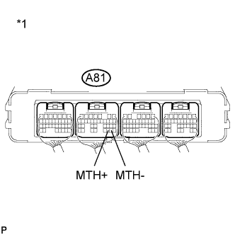
Text in Illustration *1 Component with harness connected
(Power Management Control ECU)
Measure the resistance according to the value(s) in the table below.
Standard Resistance Tester Connection Switch Condition Specified Condition A81-30 (MTH+) - A81-29 (MTH-) Power switch off 109 to 131 Ω Result Result Proceed to OK A NG (for LHD) B NG (for RHD) C -
Connect the power management control ECU connector.
B
REPLACE POWER MANAGEMENT CONTROL ECU (for LHD) Click here
C
REPLACE POWER MANAGEMENT CONTROL ECU (for RHD) Click here
A
REPLACE INVERTER WITH CONVERTER ASSEMBLY Click here
-
-
REPLACE FUSE (PCU)
-
Text in Illustration *1 Engine Room Relay Block No. 2 *2 PCU Fuse Replace the PCU fuse.
-
Turn the power switch on (READY).
-
Check if there is an open circuit in the PCU fuse in engine room relay block No. 2.
OK There is no open circuit in the PCU fuse. Tech Tips
If the fuse does not become open again after turning the power switch on (READY), it can be assumed that the previous fuse failed due to age.
-
Turn the power switch off.
NG
CHECK HARNESS AND CONNECTOR (INVERTER WITH CONVERTER ASSEMBLY - PCU FUSE) Click here
OK
COMPLETED
-
-
CHECK HARNESS AND CONNECTOR (INVERTER WITH CONVERTER ASSEMBLY - PCU FUSE)
CAUTION:
Be sure to wear insulated gloves.
-
Check that the service plug grip is not installed.
Note
After removing the service plug grip, do not turn the power switch on (READY), unless instructed by the repair manual because this may cause a malfunction.
-
Text in Illustration *1 Engine Room Relay Block No. 2 *2 PCU Fuse Remove the PCU fuse from the engine room relay block No. 2.
-
Disconnect the A79 connector from the inverter with converter assembly.
-
Measure the resistance according to the value(s) in the table below.
Text in Illustration *1 Front view of wire harness connector
(to Inverter with Converter Assembly)
*2 Engine Room Relay Block No. 2 *3 PCU Fuse - - Standard Resistance (Check for Open) Tester Connection Switch Condition Specified Condition A79-30 (+B) - 2 (PCU fuse) Power switch off Below 1 Ω A79-31 (+B2) - 2 (PCU fuse) Power switch off Below 1 Ω Standard Resistance (Check for Short) Tester Connection Switch Condition Specified Condition A79-30 (+B) or A79-31 (+B2) or 2 (PCU fuse) - Body ground and other terminals Power switch off 10 kΩ or higher -
Connect the inverter with converter assembly connector.
-
Install the PCU fuse.
NG
REPAIR OR REPLACE HARNESS OR CONNECTOR Click here
OK
-
-
REPLACE INVERTER WITH CONVERTER ASSEMBLY
-
Replace the inverter with converter assembly Click here.
NEXT
REPLACE FUSE (PCU)
-
-
REPAIR OR REPLACE HARNESS OR CONNECTOR
NEXT
REPLACE FUSE (PCU)