HYBRID BATTERY SYSTEM, Diagnostic DTC:P0A84-123

| DTC Code | DTC Name |
|---|---|
| P0A84-123 | Hybrid Battery Pack Cooling Fan 1 |
DESCRIPTION
-
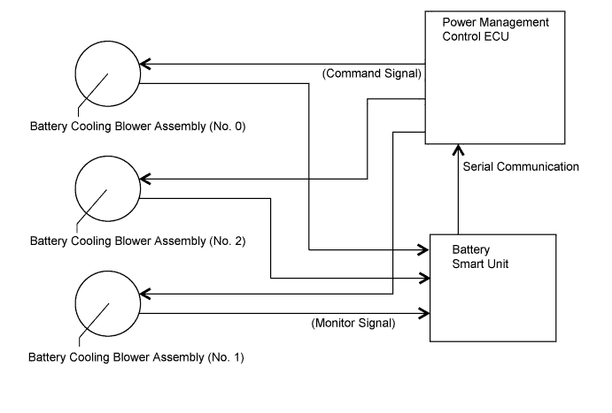
The speed of the battery blower assembly is controlled by the power management control ECU . Battery blower assembly power is supplied from the FCTL terminal of the power management control ECU by the battery blower relay when it is turned on. The power management control ECU sends command signals (S0, S1 and S2) to each battery blower assembly to get the fan speed corresponding to the HV battery temperature. Information of the voltage applied to each battery blower assembly (VM0, VM1 and VM2) is sent to the power management control ECU as a monitor signal via serial communication by the battery smart unit.
| DTC No. | DTC Detection Condition | Trouble Area |
|---|---|---|
| P0A84-123 | Voltage at battery cooling blower assembly (VM0) is out of the predetermined range in proportion to the target control voltage (1 trip detection). |
|
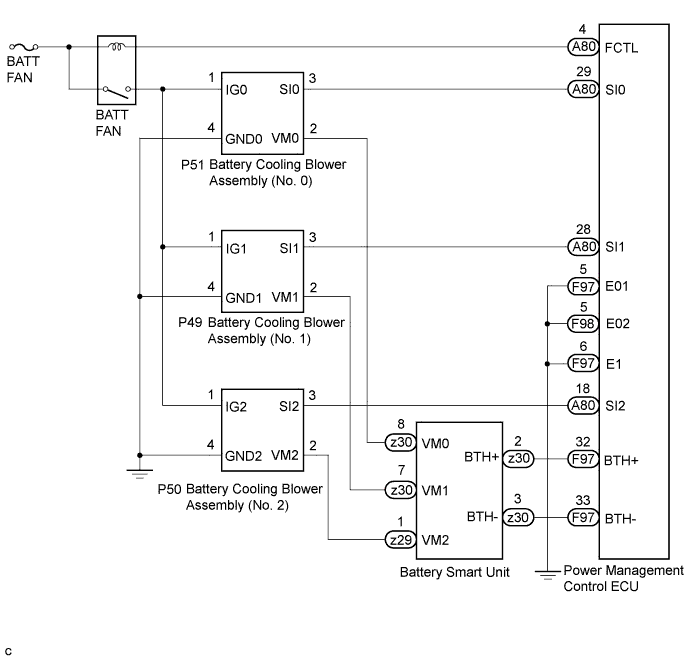
WIRING DIAGRAM
INSPECTION PROCEDURE
Note
After the power switch is turned off, the display and navigation module display (HDD navigation system) records various types of memory and settings. As a result, after turning the power switch off, make sure to wait for the time specified in the following table before disconnecting the cable from the negative (-) battery terminal.
| Specification | Waiting Time |
|---|---|
| w/o Telematics transceiver | 60 sec. |
| w/ Telematics transceiver | 120 sec. |
PROCEDURE
-
CHECK DTC OUTPUT (DTC P0AFC-123 IS OUTPUT)
-
Connect the intelligent tester to the DLC3.
-
Turn the power switch on (IG).
-
Enter the following menus: Powertrain / Hybrid Control / Trouble Codes.
-
Read output DTCs Click here.
Result Result Proceed to P0AFC-123 is not output. A P0AFC-123 is also output. B -
Disconnect the intelligent tester from the DLC3.
B 
GO TO DTC CHART
A 
-
-
CHECK DTC OUTPUT (HV)
-
Connect the intelligent tester to the DLC3.
-
Turn the power switch on (IG).
-
Read output DTCs Click here.
Result Result Proceed to P0A84-123 is output A P0A84-123, P0A99-123, and P0AD2-123 are output B -
Remove the intelligent tester from the DLC3.
B 
CHECK FUSE (BATT FAN) Click here
A
-
-
CHECK BATTERY COOLING BLOWER ASSEMBLY (NO. 0)
CAUTION:
Be sure to wear insulated gloves and protective goggles.
-
Disconnect the cable from the negative (-) battery terminal.
-
Check that the service plug grip is not installed.
Note
After removing the service plug grip, do not turn the power switch on (READY), unless instructed by the repair manual because this may cause a malfunction.
-
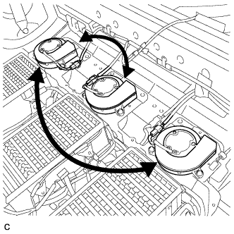
Remove the battery cover and switch the battery cooling blower assembly (No. 0) with one of the other battery cooling blower assemblies Click here.
-
Install the battery cover Click here.
-
Connect the cable to the negative (-) battery terminal.
-
Connect the intelligent tester to the DLC3.
-
Turn the power switch on (IG).
-
Enter the following menus: Powertrain / Hybrid Control / Active Test / Driving the Battery Cooling Fan.
Tech Tips
When the power switch is turned on (IG) for the first time after reconnecting the battery, the battery cooling fans operate as an initial check. Therefore, even before the active test is performed, the malfunction may be reproduced as a result of the initial check.
-
Check if the blower assembly malfunctions in a different location while operating the cooling fans (battery cooling blower assemblies).
Result Result Proceed to Malfunction is not reproduced in same blower when it is moved to another location A Malfunction is reproduced in same blower when it is moved to another location B -
Disconnect the intelligent tester from the DLC3.
-
Return the battery cooling blower assemblies to their original positions.
B
REPLACE BATTERY COOLING BLOWER ASSEMBLY (NO. 0) Click here
A
-
-
CHECK HARNESS AND CONNECTOR (BATT FAN RELAY - BATTERY COOLING BLOWER ASSEMBLY (NO. 0))
CAUTION:
Be sure to wear insulated gloves and protective goggles.
-
Disconnect the cable from the negative (-) battery terminal.
-
Check that the service plug grip is not installed.
Note
After removing the service plug grip, do not turn the power switch on (READY), unless instructed by the repair manual because this may cause a malfunction.
-
Remove the battery cover Click here.
-
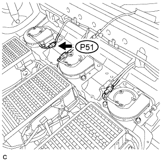
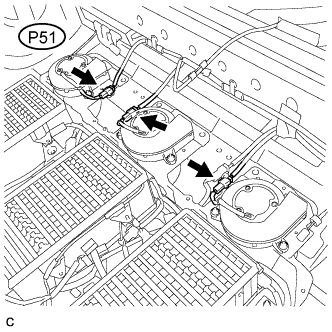
Disconnect the P51 connector from the battery cooling blower assembly (No. 0).
-
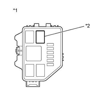
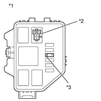
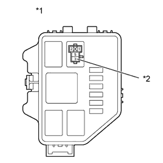
Text in Illustration *1 Engine Room Relay Block No. 3 *2 BATT FAN Relay Remove the BATT FAN relay.
-
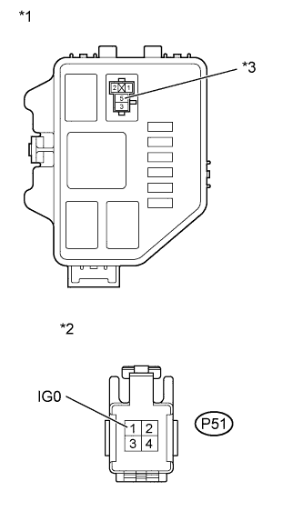
Text in Illustration *1 Engine Room Relay Block No. 3 *2 Front view of wire harness connector
(to Battery Cooling Blower Assembly (No. 0))
*3 BATT FAN relay terminal 5 Measure the resistance according to the value(s) in the table below.
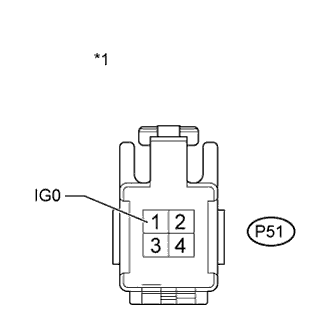
Standard Resistance Tester Connection Switch Condition Specified Condition BATT FAN relay terminal 5 - P51-1 (IG0) Power switch off Below 1 Ω Note
When taking a measurement with a tester, do not apply excessive force to the tester probe to avoid damaging the holder.
-
Install the BATT FAN relay to the engine room relay block No. 3 .
-
Connect the P51 connector to the battery cooling blower assembly (No. 0).
-
Install the battery cover Click here.
-
Connect the cable to the negative (-) battery terminal.
NG
REPAIR OR REPLACE HARNESS OR CONNECTOR
OK
-
-
CHECK HARNESS AND CONNECTOR (BATTERY COOLING BLOWER ASSEMBLY (NO. 0) - BATTERY SMART UNIT)
CAUTION:
Be sure to wear insulated gloves and protective goggles.
-
Disconnect the cable from the negative (-) battery terminal.
-
Check that the service plug grip is not installed.
Note
After removing the service plug grip, do not turn the power switch on (READY), unless instructed by the repair manual because this may cause a malfunction.
-
Remove the battery cover Click here.
-
Disconnect the P51 connector from the battery cooling blower assembly (No. 0).
-
Remove the battery smart unit Click here.
Tech Tips
Disconnect only the z30 connector of the battery smart unit.
-
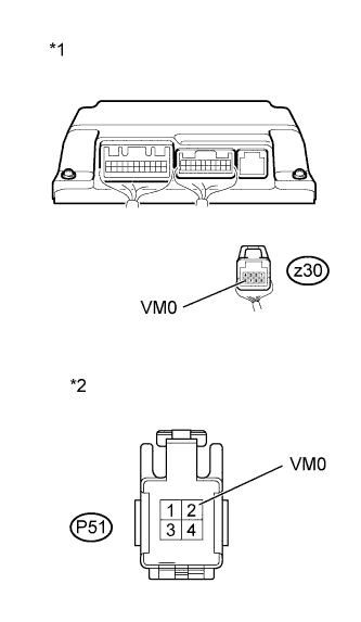
Text in Illustration *1 Rear view of wire harness connector
(to Battery Smart Unit)
*2 Front view of wire harness connector
(to Battery Cooling Blower Assembly No. 0))
Measure the resistance according to the value(s) in the table below.
Standard Resistance (Check for Open) Tester Connection Switch Condition Specified Condition z30-8 (VM0) - P51-2 (VM0) Power switch off Below 1 Ω Standard Resistance (Check for Short) Tester Connection Switch Condition Specified Condition P51-2 (VM0) or z30-3 (VM0) - Body ground Power switch off 10 kΩ or more -
Connect the P51 connector to the battery cooling blower assembly (No. 0).
-
Install the battery smart unit Click here.
-
Install the battery cover.
-
Connect the cable to the negative (-) battery terminal.
NG
REPAIR OR REPLACE HARNESS OR CONNECTOR
OK
-
-
CHECK HARNESS AND CONNECTOR (BATTERY COOLING BLOWER ASSEMBLY (NO. 0) - BODY GROUND)
CAUTION:
Be sure to wear insulated gloves and protective goggles.
-
Disconnect the cable from the negative (-) battery terminal.
-
Check that the service plug grip is not installed.
Note
After removing the service plug grip, do not turn the power switch on (READY), unless instructed by the repair manual because this may cause a malfunction.
-
Remove the battery cover Click here.
-
Disconnect the P51 connector from the battery cooling blower assembly (No. 0).
-
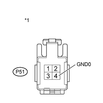
Text in Illustration *1 Front view of wire harness connector
(to Battery Cooling Blower Assembly (No. 0))
Measure the resistance according to the value(s) in the table below.
Standard Resistance Tester Connection Switch Condition Specified Condition P51-4 (GND0) - Body ground Power switch off Below 1 Ω -
Connect the P51 connector to the battery cooling blower assembly (No. 0).
-
Install the battery cover Click here.
-
Connect the cable to the negative (-) battery terminal.
NG
REPAIR OR REPLACE HARNESS OR CONNECTOR
OK
-
-
CHECK HARNESS AND CONNECTOR (POWER MANAGEMENT CONTROL ECU - COOLING BLOWER (NO. 0))
CAUTION:
Be sure to wear insulated gloves and protective goggles.
-
Disconnect the cable from the negative (-) battery terminal.
-
Check that the service plug grip is not installed.
Note
After removing the service plug grip, do not turn the power switch on (READY), unless instructed by the repair manual because this may cause a malfunction.
-
Remove the battery cover Click here.
-
Disconnect the P51 connector from the battery cooling blower assembly (No. 0).
-
Disconnect the A80 connector from the power management control ECU.
-
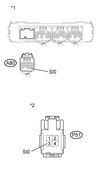
Text in Illustration *1 Rear view of wire harness connector
(to Power Management Control ECU)
*2 Front view of wire harness connector
(to Battery Cooling Blower Assembly (No. 0))
Measure the resistance according to the value(s) in the table below.
Standard Resistance (Check for Open) Tester Connection Switch Condition Specified Condition P51-3 (SI0) - A80-29 (SI0) Power switch off Below 1 Ω Standard Resistance (Check for Short) Tester Connection Switch Condition Specified Condition P51-3 (SI0) or A80-29 (SI0) - Body ground Power switch off 10 kΩ or more -
Connect the A80 connector to the power management control ECU.
-
Connect the P51 connector to the battery cooling blower assembly (No. 0).
-
Install the battery cover Click here.
-
Connect the cable to the negative (-) battery terminal.
NG
REPAIR OR REPLACE HARNESS OR CONNECTOR
OK
-
-
CHECK POWER MANAGEMENT CONTROL ECU
-
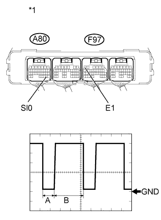
Text in Illustration *1 Component with harness connected:
(Power Management Control ECU)
Using an oscilloscope, measure the waveform according to the condition in the table below.
Item Contents Terminal A80-29 (SI0) - F97-6 (E1) Equipment Setting 1 V/DIV, 50 μs/DIV Condition Power switch on (IG or READY) Standard The waveform in the illustration can be measured. Tech Tips
-
A and B in the DUTY waveform shown in the illustration vary depending on the cooling fan mode.
-
Duty command value is influenced by variance in fan motors and the change of power supply voltage.
-
Measure when the vehicle comes to a stop and an idling stop.
Result Result Proceed to OK A NG (for LHD) B NG (for RHD) C -
-
Remove the oscilloscope from the power management control ECU.
B
REPLACE POWER MANAGEMENT CONTROL ECU (for LHD) Click here
C
REPLACE POWER MANAGEMENT CONTROL ECU (for RHD) Click here
A 
REPLACE BATTERY SMART UNIT Click here
-
-
CHECK FUSE (BATT FAN)
-
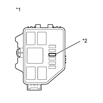
Text in Illustration *1 Engine Room Relay Block No. 3 *2 BATT FAN Fuse Remove the BATT FAN fuse from the Engine Room Relay Block No. 3.
-
Measure the resistance of the BATT FAN fuse.
Standard Resistance Tester Connection Condition Specified Condition BATT FAN fuse Always Below 1 Ω -
Install the BATT FAN fuse.
NG
CHECK HARNESS AND CONNECTOR (BATT FAN RELAY - BODY GROUND) Click here
OK
-
-
CHECK RELAY (BATT FAN)
-
Text in Illustration *1 Engine Room Relay Block No. 3 *2 BATT FAN Relay Remove the BATT FAN relay.
-
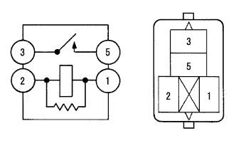
Measure the resistance according to the value(s) in the table below.
Standard Resistance Tester Connection Condition Specified Condition 3-5 Auxiliary battery voltage is not applied between terminals 1 and 2 10 kΩ or more Auxiliary battery voltage is applied between terminals 1 and 2 Below 1 Ω -
Install the BATT FAN relay.
NG
REPLACE RELAY (BATT FAN)
OK
-
-
CHECK HARNESS AND CONNECTOR (BATT FAN RELAY - BATT FAN FUSE)
-
Remove the BATT FAN relay.
-
Remove the BATT FAN fuse.
-
Text in Illustration *1 No. 3 Engine Room Relay Block *2 BATT FAN Relay Holder *3 BATT FAN Fuse Holder Measure the resistance according to the value(s) in the table below.
Standard Resistance Tester Connection Switch Condition Specified Condition BATT FAN fuse terminal 2 - BATT FAN relay terminal 1 Power switch off Below 1 Ω BATT FAN fuse terminal 2 - BATT FAN relay terminal 3 Below 1 Ω Note
When taking a measurement with a tester, do not apply excessive force to the tester probe to avoid damaging the holder.
-
Install the BATT FAN relay and BATT FAN fuse.
NG
REPLACE ENGINE ROOM RELAY BLOCK NO.3
OK
-
-
CHECK HARNESS AND CONNECTOR (BATT FAN RELAY - BATTERY COOLING BLOWER ASSEMBLY (NO. 0))
CAUTION:
Be sure to wear insulated gloves and protective goggles.
-
Disconnect the cable from the negative (-) battery terminal.
-
Check that the service plug grip is not installed.
Note
After removing the service plug grip, do not turn the power switch on (READY), unless instructed by the repair manual because this may cause a malfunction.
-
Text in Illustration *1 Engine Room Relay Block No. 3 *2 BATT FAN Relay Remove the BATT FAN relay.
-
Remove the battery cover Click here.
-
Disconnect the P51 connector from the battery cooling blower assembly (No. 0).
-
Text in Illustration *1 Engine Room Relay Block No. 3 *2 Front view of wire harness connector
(to Battery Cooling Blower Assembly (No. 0))
*3 BATT FAN relay terminal 5 Measure the resistance according to the value(s) in the table below.
Standard Resistance Tester Connection Switch Condition Specified Condition BATT FAN relay terminal 5 - P51-1 (IG0) Power switch off Below 1 Ω Note
When taking a measurement with a tester, do not apply excessive force to the tester probe to avoid damaging the holder.
-
Connect the P51connector to the battery cooling blower assembly (No. 0).
-
Install the battery cover Click here.
-
Install the BATT FAN relay.
-
Connect the cable to the negative (-) battery terminal.
NG
REPAIR OR REPLACE HARNESS OR CONNECTOR
OK
-
-
CHECK HARNESS AND CONNECTOR (BATT FAN RELAY - POWER MANAGEMENT CONTROL ECU)
-
Text in Illustration *1 Engine Room Relay Block No. 3 *2 BATT FAN Relay Remove the BATT FAN relay.
-
Disconnect the A80 connector from the power management control ECU.
-
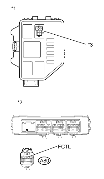
Text in Illustration *1 No. 3 Engine Room Relay Block *2 Rear view of wire harness connector:
(to Power Management Control ECU)
*3 BATT FAN Relay Holder Measure the resistance according to the value(s) in the table below.
Standard Resistance (Check for Open) Tester Connection Switch Condition Specified Condition BATT FAN relay terminal 2 - A80-4 (FCTL) Power switch off Below 1 Ω Standard Resistance (Check for Short) Tester Connection Switch Condition Specified Condition BATT FAN relay terminal 2 or A80-4 (FCTL) -Body ground Power switch off 10 kΩ or higher Note
When taking a measurement with a tester, do not apply excessive force to the tester probe to avoid damaging the holder.
-
Connect the A80 connector to the power management control ECU.
-
Install the BATT FAN relay.
NG
REPAIR OR REPLACE HARNESS OR CONNECTOR
OK
-
-
CHECK HARNESS AND CONNECTOR (POWER MANAGEMENT CONTROL ECU - BODY GROUND)
-
Disconnect the A97 connector from the power management control ECU.
-
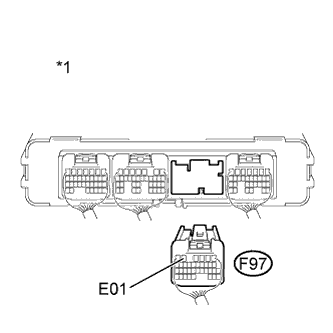
Text in Illustration *1 Rear view of wire harness connector
(to Power Management Control ECU)
Measure the resistance according to the value(s) in the table below.
Standard Resistance Tester Connection Switch Condition Specified Condition F97-5 (E01) - Body ground Power switch off Below 1 Ω Note
When taking a measurement with a tester, do not apply excessive force to the tester probe to avoid damaging the holder.
-
Connect the A97connector to the power management control ECU.
NG
REPAIR OR REPLACE HARNESS OR CONNECTOR
OK
-
-
CHECK HARNESS AND CONNECTOR (POWER MANAGEMENT CONTROL ECU - BODY GROUND)
-
Disconnect the A98 connector from the power management control ECU.
-
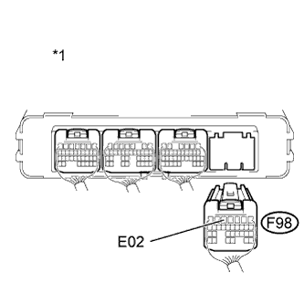
Text in Illustration *1 Rear view of wire harness connector
(to Power Management Control ECU)
Measure the resistance according to the value(s) in the table below.
Standard Resistance Tester Connection Switch Condition Specified Condition F98-5(E02) - Body ground Power switch off Below 1 Ω Note
When taking a measurement with a tester, do not apply excessive force to the tester probe to avoid damaging the holder.
Result Result Proceed to OK (for LHD) A OK (for RHD) B NG C -
Connect the A98 connector to the power management control ECU.
B
REPLACE POWER MANAGEMENT CONTROL ECU (for RHD) Click here
C
REPAIR OR REPLACE HARNESS OR CONNECTOR
A
REPLACE POWER MANAGEMENT CONTROL ECU (for LHD) Click here
-
-
CHECK HARNESS AND CONNECTOR (BATT FAN RELAY - BODY GROUND)
-
Text in Illustration *1 Engine Room Relay Block No. 3 *2 BATT FAN relay terminal 3 Remove the BATT FAN relay.
-
Measure the resistance according to the value(s) in the table below.
Standard Resistance Tester Connection Switch Condition Specified Condition BATT FAN relay terminal 3 - Body ground Power switch off 10 kΩ or higher Note
When taking a measurement with a tester, do not apply excessive force to the tester probe to avoid damaging the holder.
-
Install the BATT FAN relay.
NG
REPAIR OR REPLACE HARNESS OR CONNECTOR Click here
OK
-
-
CHECK HARNESS AND CONNECTOR (BATTERY COOLING BLOWER ASSEMBLY - BODY GROUND)
CAUTION:
Be sure to wear insulated gloves and protective goggles.
-
Disconnect the cable from the negative (-) battery terminal.
-
Check that the service plug grip is not installed.
Note
After removing the service plug grip, do not turn the power switch on (READY), unless instructed by the repair manual because this may cause a malfunction.
-
Remove the battery cover Click here.
-
Disconnect each of the 3 battery cooling blower assembly connectors.
-
Text in Illustration *1 Front view of wire harness connector
(to Battery Cooling Blower Assembly)
Measure the resistance according to the value(s) in the table below.
Standard Resistance Tester Connection Switch Condition Specified Condition P51-1 (IG0) - Body ground Power switch off 10 kΩ or higher -
Connect each of the 3 battery cooling blower assembly connectors.
-
Install the battery cover Click here.
-
Connect the cable to the negative (-) battery terminal.
NG
REPAIR OR REPLACE HARNESS OR CONNECTOR Click here
OK
-
-
CHECK BATTERY COOLING BLOWER ASSEMBLY
CAUTION:
Be sure to wear insulated gloves and protective goggles.
-
Disconnect the cable from the negative (-) battery terminal.
-
Check that the service plug grip is not installed.
Note
After removing the service plug grip, do not turn the power switch on (READY), unless instructed by the repair manual because this may cause a malfunction.
-
Remove the battery cover Click here.
-
Disconnect each of the 3 battery cooling blower assembly connectors.
-
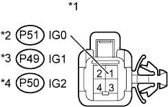
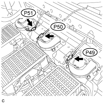
Text in Illustration *1 Component without harness connected
(Battery Cooling Blower Assembly)
*2 Battery Cooling Blower Assembly (No. 0) *3 Battery Cooling Blower Assembly (No. 1) *4 Battery Cooling Blower Assembly (No. 2) Measure the resistance according to the value(s) in the table below.
Standard Resistance Tester Connection Switch Condition Specified Condition P51-1(IG0) - Body ground Power switch off 10 kΩ or higher P49-1(IG1) - Body ground Power switch off 10 kΩ or higher P50-1(IG2) - Body ground Power switch off 10 kΩ or higher -
Connect each of the 3 battery cooling blower assembly connectors.
-
Install the battery cover Click here.
-
Connect the cable to the negative (-) battery terminal.
NG
REPLACE BATTERY COOLING BLOWER ASSEMBLY (MALFUNCTIONING BATTERY COOLING BLOWER ASSEMBLY) Click here
OK
REPLACE FUSE (BATT FAN)
-
-
REPLACE BATTERY COOLING BLOWER ASSEMBLY (MALFUNCTIONING BATTERY COOLING BLOWER ASSEMBLY)
Tech Tips
NEXT
REPLACE FUSE (BATT FAN)
-
REPAIR OR REPLACE HARNESS OR CONNECTOR
NEXT
REPLACE FUSE (BATT FAN)