HYBRID CONTROL SYSTEM, Diagnostic DTC:P3137-348, P3138-349

| DTC Code | DTC Name |
|---|---|
| P3137-348 | Collision Sensor Low Input |
| P3138-349 | Collision Sensor High Input |
DESCRIPTION
-
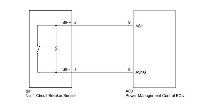
The power management control ECU (HV CPU) monitors the connection status of the No.1 circuit breaker sensor signal (collision signal) line. If the ECU detects a malfunction, it will alert the driver.
| DTC No. | INF Code | DTC Detection Condition | Trouble Area |
|---|---|---|---|
| P3137 | 348 | GND short in No. 1 circuit breaker sensor circuit |
|
| P3138 | 349 | Open or +B short in No. 1 circuit breaker sensor circuit |
WIRING DIAGRAM
INSPECTION PROCEDURE
PROCEDURE
-
CHECK POWER MANAGEMENT CONTROL ECU (VOLTAGE CHECK)
-
Turn the power switch on (IG).
-
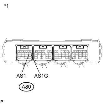
Text in Illustration *1 Component with harness connected
(Power Management Control ECU)
Measure the voltage according to the value(s) in the table below.
Standard Voltage Tester Connection Switch Condition Specified Condition A80-9 (AS1) - A80-8 (AS1G) Power switch on (IG) 2.3 to 3.1 V -
Turn the power switch off.
NG 
INSPECT NO.1 CIRCUIT BREAKER SENSOR Click here
OK 
-
-
CLEAR DTC (HV)
-
Connect the intelligent tester to the DLC3.
-
Turn the power switch on (IG).
-
Enter the following menus: Powertrain / Hybrid Control / Trouble Codes.
-
Read and record the DTCs and freeze frame data.
-
Clear DTCs and freeze frame data.
-
Turn the power switch off.
NEXT
-
-
CHECK DTC OUTPUT (HV)
-
Connect the intelligent tester to the DLC3.
-
Turn the power switch on (IG).
-
Enter the following menus: Powertrain / Hybrid Control / Trouble Codes.
-
Check if DTCs are output.
Result Result Proceed to DTC P3137-348, P3138-349 is output. for LHD A for RHD B DTC P3137-348, P3138-349 is not output. C -
Turn the power switch off.
B 
REPLACE POWER MANAGEMENT CONTROL ECU (for RHD) Click here
C
CHECK FOR INTERMITTENT PROBLEMS Click here
A 
REPLACE POWER MANAGEMENT CONTROL ECU (for LHD) Click here
-
-
INSPECT NO.1 CIRCUIT BREAKER SENSOR
-
Disconnect the g9 connector from the No. 1 circuit breaker sensor.
-
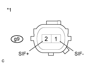
Text in Illustration *1 Component without harness connected
(No. 1 Circuit Breaker Sensor)
Measure the resistance according to the value(s) in the table below.
Standard Resistance Tester Connection Switch Condition Specified Condition g9-1 (SIF-) - g9-2 (SIF+) Power switch off
(20°C)
0.65 to 1.0 kΩ -
Connect the No. 1 circuit breaker sensor connector.
NG
REPLACE NO.1 CIRCUIT BREAKER SENSOR Click here
OK
REPAIR OR REPLACE HARNESS OR CONNECTOR
-