HYBRID CONTROL SYSTEM, Diagnostic DTC:P3107-213

| DTC Code | DTC Name |
|---|---|
| P3107-213 | Airbag ECU Communication Circuit Malfunction |
DESCRIPTION
-
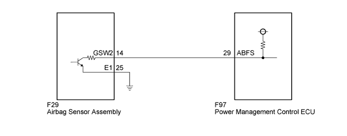
The power management control ECU (HV CPU) detects a problem in the collision signal line from the airbag sensor assembly and alerts the driver.
| DTC No. | INF Code | DTC Detection Condition | Trouble Area |
|---|---|---|---|
| P3107 | 213 | Short to GND in the communication circuit |
|
WIRING DIAGRAM
INSPECTION PROCEDURE
PROCEDURE
-
CHECK DTC OUTPUT (AIRBAG)
-
Connect the intelligent tester to the DLC3.
-
Turn the power switch on (IG).
-
Enter the following menus: Body Electrical / SRS Airbag / Trouble Codes.
-
Check if DTCs are output.
Result Result Proceed to Airbag system DTCs are not output. A Airbag system DTCs are output. B -
Turn the power switch off.
B 
GO TO DTC CHART Click here
A 
-
-
CHECK AIRBAG SENSOR ASSEMBLY (CHECK WAVEFORM)
-
Turn the power switch on (READY).
-
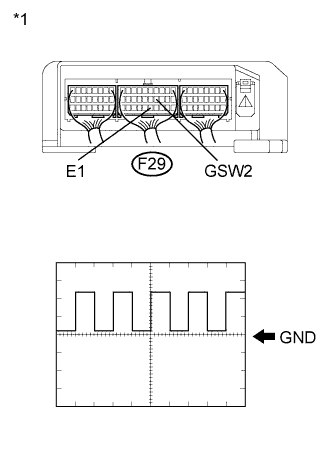
Text in Illustration *1 Component with harness connected
(Airbag Sensor Assembly)
Connect an oscilloscope between the airbag sensor assembly terminals specified in the table below, and measure the waveform.
Item Contents Terminal F29-14 (GSW2) - F29-25 (E1) Equipment Setting 5V/DIV, 500ms/DIV Condition Power switch on (READY) Result Result Proceed to The waveform appears as shown in the illustration. A The waveform differs from the one shown in the illustration. B -
Turn the power switch off.
B 
CHECK AIRBAG SENSOR ASSEMBLY Click here
A
-
-
CLEAR DTC
-
Connect the intelligent tester to the DLC3.
-
Turn the power switch on (IG).
-
Enter the following menus: Powertrain / Hybrid Control / Trouble Codes.
-
Read and record the DTCs and freeze frame data.
-
Clear DTCs and freeze frame data.
-
Turn the power switch off.
NEXT
-
-
CHECK DTC OUTPUT (HV)
-
Connect the intelligent tester to the DLC3.
-
Turn the power switch on (IG).
-
Enter the following menus: Powertrain / Hybrid Control / Trouble Codes.
-
Check if DTCs are output.
Result Result Proceed to DTC P3107-213 is not output. A DTC P3107-213 is output. for LHD B for RHD C -
Turn the power switch off.
B
REPLACE POWER MANAGEMENT CONTROL ECU (for LHD) Click here
C
REPLACE POWER MANAGEMENT CONTROL ECU (for RHD) Click here
A
-
-
CHECK FOR INTERMITTENT PROBLEMS
-
Check for intermittent problems Click here.
Result Result Proceed to OK (for LHD) A OK (for RHD) B NG C
B
REPLACE POWER MANAGEMENT CONTROL ECU (for RHD) Click here
C
REPAIR OR REPLACE MALFUNCTIONING PARTS, COMPONENT AND AREA
A 
REPLACE POWER MANAGEMENT CONTROL ECU (for LHD) Click here
-
-
CHECK AIRBAG SENSOR ASSEMBLY
-
Disconnect the F29 connector from the airbag sensor assembly.
-
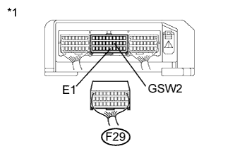
Text in Illustration *1 Component without harness connected
(Airbag Sensor Assembly)
Measure the resistance according to the value(s) in the table below.
Standard Resistance Tester Connection Switch Condition Specified Condition F29-14 (GSW2) - F29-25 (E1) Power switch off 10 kΩ or higher -
Connect the airbag sensor assembly connector.
NG
REPLACE AIRBAG SENSOR ASSEMBLY Click here
OK
-
-
CHECK HARNESS AND CONNECTOR (POWER MANAGEMENT CONTROL ECU - AIRBAG SENSOR ASSEMBLY)
-
Disconnect the F29 connector from the airbag sensor assembly.
-
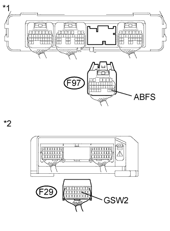
Text in Illustration *1 Rear view of wire harness connector
(to Power Management Control ECU)
*2 Rear view of wire harness connector
(to Airbag Sensor Assembly)
Disconnect the F97 connector from the power management control ECU.
-
Measure the resistance according to the value(s) in the table below.
Standard Resistance Tester Connection Switch Condition Specified Condition F97-29 (ABFS) or F29-14 (GSW2) - Body ground and other terminals Power switch off 10 kΩ or higher Result Result Proceed to OK (for LHD) A OK (for RHD) B NG C -
Connect the airbag sensor assembly connector.
-
Connect the power management control ECU connector.
B
REPLACE POWER MANAGEMENT CONTROL ECU (for RHD) Click here
C
REPAIR OR REPLACE HARNESS OR CONNECTOR
A
REPLACE POWER MANAGEMENT CONTROL ECU (for LHD) Click here
-