HYBRID CONTROL SYSTEM, Diagnostic DTC:P3232-749

| DTC Code | DTC Name |
|---|---|
| P3232-749 | Short to GND in Blocking of HV Gate Connection |
DESCRIPTION
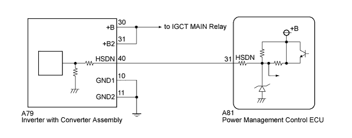
The power management control ECU (HV CPU) sends a shutdown signal to the inverter with converter assembly (MG ECU) to shut down the power supply to MG2 and MG1.
| DTC No. | INF Code | DTC Detection Condition | Trouble Area |
|---|---|---|---|
| P3232 | 749 | Short to GND in the emergency shutdown signal line while the IGBTs are being shut down. |
|
WIRING DIAGRAM
INSPECTION PROCEDURE
Tech Tips
When attempting to reproduce the problem, turning the power switch on (IG) and off repeatedly makes it easier to reproduce the problem. Do not repeatedly turn the power switch on (READY) and off as this will activate a system main relay overheat protection.
PROCEDURE
-
CHECK HARNESS AND CONNECTOR (POWER MANAGEMENT CONTROL ECU - INVERTER WITH CONVERTER)
CAUTION:
Be sure to wear insulated gloves.
-
Check that the service plug grip is not installed.
Note
After removing the service plug grip, do not turn the power switch on (READY), unless instructed by the repair manual because this may cause a malfunction.
-
Disconnect connector A79 from the inverter with converter assembly.
-
Disconnect connector A81 from the power management control ECU.
-
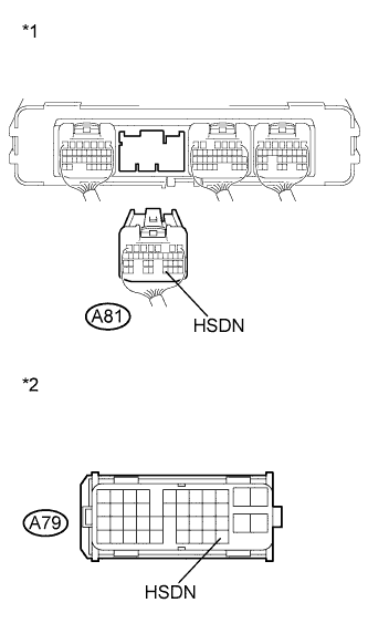
Text in Illustration *1 Rear view of wire harness connector
(to Power Management Control ECU)
*2 Front view of wire harness connector
(to Inverter with Converter Assembly)
Measure the resistance according to the value(s) in the table below.
Standard Resistance Tester Connection Switch Condition Specified Condition A81-31 (HSDN) or A79-40 (HSDN) - Body ground and other terminals Power switch off 10 kΩ or higher -
Connect the power management control ECU connector.
-
Connect the inverter with converter assembly connector.
NG 
REPAIR OR REPLACE HARNESS OR CONNECTOR
OK 
-
-
CHECK INVERTER WITH CONVERTER ASSEMBLY
CAUTION:
Be sure to wear insulated gloves.
-
Check that the service plug grip is not installed.
Note
After removing the service plug grip, do not turn the power switch on (READY), unless instructed by the repair manual because this may cause a malfunction.
-
Disconnect connector A79 from the inverter with converter assembly.
-
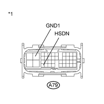
Text in Illustration *1 Component with harness connected
(Inverter with Converter Assembly)
Measure the resistance according to the value(s) in the table below.
Standard Resistance Tester Connection Switch Condition Specified Condition A79-40 (HSDN) - A79-10(GND1) Power switch off 2.65 to 3.55 kΩ Result Result Proceed to NG A OK (for LHD) B OK (for RHD) C -
Connect the inverter with converter assembly connector.
B
REPLACE POWER MANAGEMENT CONTROL ECU (for LHD) Click here
C
REPLACE POWER MANAGEMENT CONTROL ECU (for RHD) Click here
A 
REPLACE INVERTER WITH CONVERTER ASSEMBLY Click here
-