HYBRID CONTROL SYSTEM, Diagnostic DTC:P2603-768

| DTC Code | DTC Name |
|---|---|
| P2603-768 | Oil Pump Control Circuit High |
DESCRIPTION
Refer to the description for DTC P2601-777 Click here.
| DTC No. | INF Code | DTC Detection Condition | Trouble Area |
|---|---|---|---|
| P2603 | 768 |
|
|
WIRING DIAGRAM
Refer to the wiring diagram for DTC P2601-777 Click here.
INSPECTION PROCEDURE
Tech Tips
When troubleshooting the oil pump with motor assembly, check for the following conditions.
-
ATF temperature inside the oil cooler is 5°C (41°F) or more.
-
The ambient temperature sensor value is 5°C (41°F) or more.
PROCEDURE
-
CHECK FUSE (OIL PMP)
-
Remove the OIL PMP fuse from the engine room relay block No. 3.
-
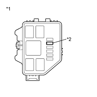
Text in Illustration *1 Engine Room Relay Block No. 3 *2 OIL PMP Fuse Measure the resistance according to the value(s) in the table below.
Standard Resistance Tester Connection Condition Specified Condition OIL PMP fuse Always Below 1Ω -
Install the OIL PMP fuse.
NG 
REPLACE FUSE (OIL PMP)
OK 
-
-
CHECK RELAY (OIL PMP)
-
Remove the OIL PMP relay from the engine room relay block No. 3.
-
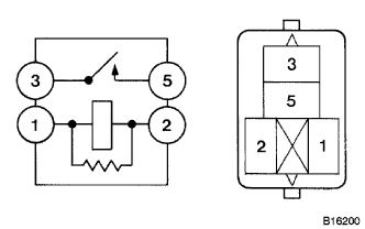
Measure the resistance according to the value(s) in the table below.
Standard Resistance Tester Connection Condition Specified Condition 1 - 2 Always 151 to 203 Ω 3 - 5 Auxiliary battery voltage is not applied between terminals 1 and 2 10 kΩ or higher Auxiliary battery voltage is applied between terminals 1 and 2 Below 1 Ω -
Install the OIL PMP relay.
NG
REPLACE RELAY (OIL PMP)
OK
-
-
CHECK HARNESS AND CONNECTOR (POWER MANAGEMENT CONTROL ECU - OIL PMP RELAY - OIL PUMP)
-
Remove the OIL PMP relay from the engine room relay block No. 3.
-
Disconnect the A75 connector from the oil pump with motor assembly.
-
Disconnect the A80 connector from the power management control ECU.
-
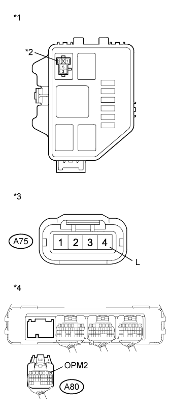
Text in Illustration *1 Engine Room Relay Block NO.3 *2 OIL PMP relay *3 Front view of wire harness connector
(to Oil Pump with Motor Assembly)
*4 Rear view of wire harness connector
(to Power Management Control ECU)
Measure the resistance according to the value(s) in the table below.
Standard Resistance (Check for Open) Tester Connection Switch Condition Specified Condition OIL PMP relay terminal 1 - A80-1 (OPM2) Power switch off Below 1 Ω Standard Resistance (Check for Short) Tester Connection Switch Condition Specified Condition OIL PMP relay terminal 1 or A80-1 (OPM2) - Body ground and other terminals Power switch off 10 kΩ or higher -
Measure the resistance according to the value(s) in the table below.
Standard Resistance (Check for Open) Tester Connection Switch Condition Specified Condition OIL PMP relay terminal 5 - A75-4 (L) Power switch off Below 1 Ω Standard Resistance (Check for Short) Tester Connection Switch Condition Specified Condition OIL PMP relay terminal 5 or A75-4 (L) - Body ground and other terminals Power switch off 10 kΩ or higher -
Connect the power management control ECU connector.
-
Connect the oil pump with motor assembly connector.
-
Install the OIL PMP relay.
NG
REPAIR OR REPLACE HARNESS OR CONNECTOR
OK
-
-
CHECK HARNESS AND CONNECTOR (POWER MANAGEMENT CONTROL ECU - OIL PUMP)
-
Disconnect the A75 connector from the oil pump with motor assembly.
-
Disconnect the A80 connector from the power management control ECU.
-
Turn the power switch on (IG).
-
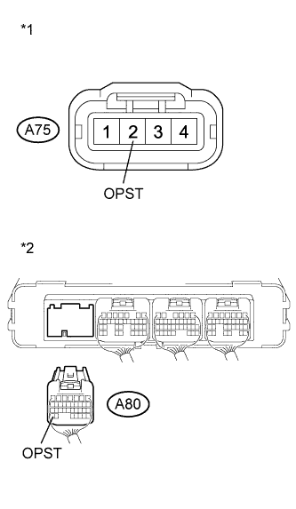
Text in Illustration *1 Front view of wire harness connector
(to Oil Pump with Motor Assembly)
*2 Rear view of wire harness connector
(to Power Management Control ECU)
Measure the voltage according to the value(s) in the table below.
Standard Voltage Tester Connection Condition Specified Condition A75-2 (OPST) or A80-34 (OPST) - Body ground Power switch on (IG) Below 1 V Note
Turning the power switch on (IG) with the power management control ECU connector disconnected causes other DTCs to be stored. Clear the DTCs after performing this inspection.
-
Turn the power switch off.
-
Measure the resistance according to the value(s) in the table below.
Standard Resistance Tester Connection Switch Condition Specified Condition A75-2 (OPST) - A80-34 (OPST) Power switch off Below 1 Ω -
Connect the power management control ECU connector.
-
Connect the oil pump with motor assembly connector.
NG
REPAIR OR REPLACE HARNESS OR CONNECTOR
OK
-
-
CHECK POWER MANAGEMENT CONTROL ECU
-
Turn the power switch on (IG).
-
Enter inspection mode Click here.
Tech Tips
Entering inspection mode activates the oil pump with motor assembly.
-
Turn the power switch on (READY).
-
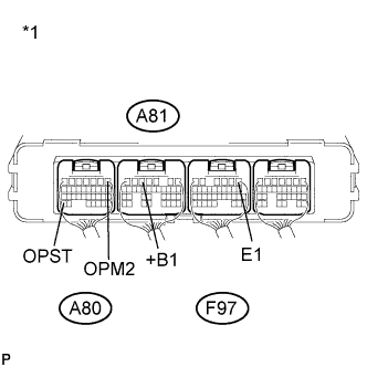
Text in Illustration *1 Component with harness connected
(Power Management Control ECU)
Measure the voltage according to the value(s) in the table below.
Standard Voltage Tester Connection Condition Specified Condition A80-1 (OPM2) - F97-6 (E1) Inspection mode
Power switch on (READY)
11 to 14 V -
Turn the power switch off.
-
Measure the resistance according to the value(s) in the table below.
Standard Resistance Tester Connection Switch Condition Specified Condition A80-34 (OPST) - A81-5 (+B1) Power switch off 10 kΩ or higher Result Result Proceed to OK A NG (for LHD) B NG (for RHD) C -
Turn the power switch off.
B
REPLACE POWER MANAGEMENT CONTROL ECU (for LHD) Click here
C
REPLACE POWER MANAGEMENT CONTROL ECU (for RHD) Click here
A 
REPLACE OIL PUMP WITH MOTOR ASSEMBLY Click here
-