HYBRID CONTROL SYSTEM, Diagnostic DTC:P2602-767

| DTC Code | DTC Name |
|---|---|
| P2602-767 | Oil Pump Control Circuit Low |
DESCRIPTION
Refer to the description for DTC P2601-777 Click here.
| DTC No. | INF Code | DTC Detection Condition | Trouble Area |
|---|---|---|---|
| P2602 | 767 |
|
|
WIRING DIAGRAM
Refer to the wiring diagram for DTC P2601-777 Click here.
INSPECTION PROCEDURE
Tech Tips
When troubleshooting the oil pump with motor assembly, check for the following conditions.
-
ATF temperature inside the oil cooler is 5°C (41°F) or more.
-
The ambient temperature sensor value is 5°C (41°F) or more.
PROCEDURE
-
CHECK HARNESS AND CONNECTOR (POWER MANAGEMENT CONTROL ECU - OIL PUMP WITH MOTOR ASSEMBLY)
-
Disconnect the A75 connector from the oil pump with motor assembly.
-
Disconnect the A80 connector from the power management control ECU.
-
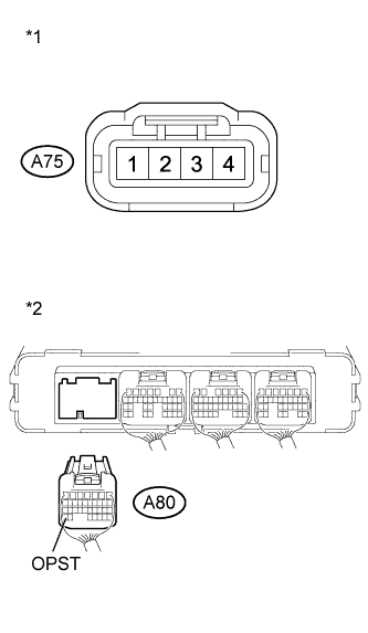
Text in Illustration *1 Front view of wire harness connector
(to Oil Pump with Motor Assembly)
*2 Rear view of wire harness connector
(to Power Management Control ECU)
Measure the resistance according to the value(s) in the table below.
Standard Resistance Tester Connection Switch Condition Specified Condition A80-34 (OPST) - Body ground Power switch off 10 kΩ or higher -
Connect the power management control ECU connector.
-
Connect the oil pump with motor assembly connector.
NG 
REPAIR OR REPLACE HARNESS OR CONNECTOR
OK 
-
-
INSPECT OIL PUMP WITH MOTOR ASSEMBLY
-
Disconnect the A75 connector from the oil pump with motor assembly.
-
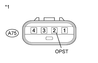
Text in Illustration *1 Component without harness connected
(Oil Pump with Motor Assembly)
Measure the resistance according to the value(s) in the table below.
Standard Resistance Tester Connection Switch Condition Specified Condition A75-2 (OPST) - Body ground Power switch off 10 kΩ or higher Result Result Proceed to OK (for LHD) A OK (for RHD) B NG C -
Connect the oil pump with motor assembly connector.
B
REPLACE POWER MANAGEMENT CONTROL ECU (for RHD) Click here
C
REPLACE OIL PUMP WITH MOTOR ASSEMBLY Click here
A 
REPLACE POWER MANAGEMENT CONTROL ECU (for LHD) Click here
-