HYBRID CONTROL SYSTEM, Diagnostic DTC:P2601-779

| DTC Code | DTC Name |
|---|---|
| P2601-779 | Oil Pump Control Circuit Range / Performance |
DESCRIPTION
Refer to the description for DTC P2601-777 Click here.
| DTC No. | INF Code | DTC Detection Condition | Trouble Area |
|---|---|---|---|
| P2601 | 779 |
|
|
WIRING DIAGRAM
Refer to the wiring diagram for DTC P2601-777 Click here.
INSPECTION PROCEDURE
Tech Tips
When troubleshooting the oil pump with motor assembly, check for the following conditions.
-
ATF temperature inside the oil cooler is 5°C (41°F) or more.
-
The ambient temperature sensor value is 5°C (41°F) or more.
PROCEDURE
-
CHECK DTC OUTPUT (HV)
-
Connect the intelligent tester to the DLC3.
-
Turn the power switch on (IG).
-
Enter the following menus: Powertrain / Hybrid Control / Trouble Codes.
-
Check if DTCs are output.
Result Result Proceed to P2601-779 only is output. A P0A08-264 is also output. B -
Turn the power switch off.
B 
GO TO DTC CHART Click here
A 
-
-
CHECK FUSE (OIL PMP)
-
Remove the OIL PMP fuse from the engine room relay block No. 3.
-
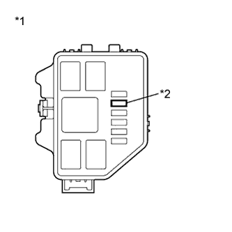
Text in Illustration *1 Engine Room Relay Block No. 3 *2 OIL PMP Fuse Measure the resistance according to the value(s) in the table below.
Standard Resistance Tester Connection Condition Specified Condition OIL PMP fuse Always Below 1Ω -
Install the OIL PMP fuse.
NG
REPLACE FUSE (OIL PMP)
OK
-
-
CLEAR DTC
-
Connect the intelligent tester to the DLC3.
-
Turn the power switch on (IG).
-
Enter the following menus: Powertrain / Hybrid Control / Trouble Codes.
-
Read and record the DTCs and freeze frame data.
-
Enter the following menus: Powertrain / Hybrid Control / Trouble Codes.
-
Clear DTCs and freeze frame data.
-
Turn the power switch off.
NEXT
-
-
CHECK DTC OUTPUT (HV)
-
Connect the intelligent tester to the DLC3.
-
Turn the power switch on (IG).
-
Enter the following menus: Powertrain / Hybrid Control / Trouble Codes.
-
Check if DTCs are output.
Result Result Proceed to P0A08-264 is output. A The DTC is not output. B -
Turn the power switch off.
B
CHECK FOR INTERMITTENT PROBLEMS Click here
A
-
-
CHECK HARNESS AND CONNECTOR (AUXILIARY BATTERY - OIL PUMP - BODY GROUND)
-
Disconnect the cable from the negative auxiliary battery terminal.
-
Disconnect the cable from the positive auxiliary battery terminal.
-
Remove the OIL PMP relay from the engine room relay block No. 3.
-
Disconnect the A75 connector from the oil pump with motor assembly.
-
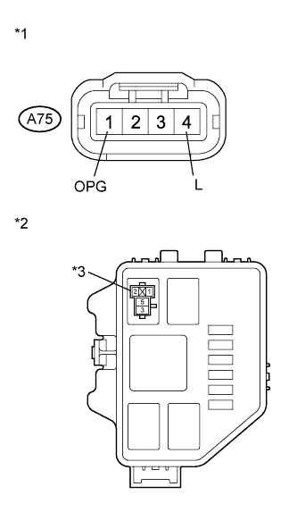
Text in Illustration *1 Front view of wire harness connector
(to Oil Pump with Motor Assembly)
*2 Engine Room Relay Block NO.3 *3 OIL PMP fuse Measure the resistance according to the value(s) in the table below.
Standard Resistance Tester Connection Switch Condition Specified Condition Resistance Positive auxiliary battery terminal - OIL PMP relay terminal 3 Power switch off Below 2 Ω R1 OIL PMP relay terminal 5 - A75-4 (L) Power switch off Below 2 Ω R2 A75-1 (OPG) - Body ground Power switch off Below 2 Ω R3 OK Combined resistance (R1, R2 and R3) of each part in the wire harness is below 6 Ω. -
Connect the oil pump with motor assembly connector.
-
Install the OIL PMP relay.
-
Connect the cable to the positive auxiliary battery terminal.
-
Connect the cable to the negative auxiliary battery terminal.
NG
REPAIR OR REPLACE HARNESS OR CONNECTOR
OK
-
-
CHECK POWER MANAGEMENT CONTROL ECU
-
Connect the intelligent tester to the DLC3.
-
Turn the power switch on (IG).
-
Enter inspection mode Click here.
Tech Tips
Entering inspection mode activates the oil pump with motor assembly.
-
Turn the power switch on (READY).
-
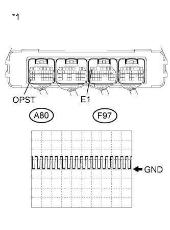
Text in Illustration *1 Component with harness connected
(Power Management Control ECU)
Connect an oscilloscope between the power management control ECU terminals specified in the table below, and measure the waveform.
Item Content Terminal A80-34 (OPST) - F97-6 (E1) Equipment Setting 10 V/DIV., 20 ms./DIV. Condition Inspection mode
Power switch on (READY)
OK The waveform appears as shown in the illustration. Result Result Proceed to OK A NG (for LHD) B NG (for RHD) C -
Turn the power switch off.
B
REPLACE POWER MANAGEMENT CONTROL ECU (for LHD) Click here
C
REPLACE POWER MANAGEMENT CONTROL ECU (for RHD) Click here
A 
REPLACE OIL PUMP WITH MOTOR ASSEMBLY Click here
-