HYBRID CONTROL SYSTEM, Diagnostic DTC:P2601-777

| DTC Code | DTC Name |
|---|---|
| P2601-777 | Oil Pump Control Circuit Range / Performance |
DESCRIPTION
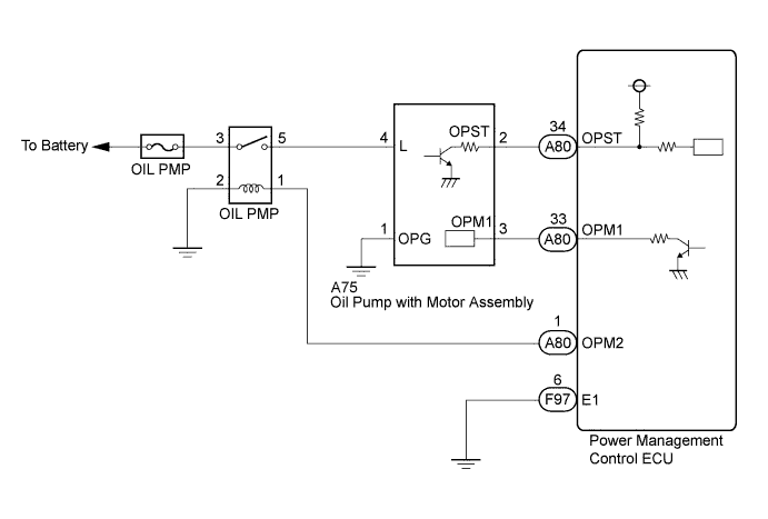
The power management control ECU (HV CPU) detects the MG1 and MG2 temperature based on signals from the generator and motor temperature sensors and activates the OIL PMP relay and oil pump driver (oil pump with motor assembly).
The power management control ECU (HV CPU) monitors OPST signals from the oil pump driver and detects malfunctions.
| DTC No. | INF Code | DTC Detection Condition | Trouble Area |
|---|---|---|---|
| P2601 | 777 | Command signal (OPM1) from power management control ECU is abnormal |
|
The oil pump with motor assembly is activated when:
1. MG1 temperature is 80°C (176°F) or more
2. MG2 temperature is 100°C (212°F) or more and the MG1 temperature is 70°C (158°F) or more
Tech Tips
The oil pump with motor assembly cannot be activated only with the OIL PMP relay on. It is activated after receiving the command signals (OPM1) from the power management control ECU.
WIRING DIAGRAM
INSPECTION PROCEDURE
Tech Tips
When troubleshooting the oil pump with motor assembly, check for the following conditions
-
ATF temperature inside the oil cooler is 5°C (41°F) or more.
-
The ambient temperature sensor value is 5°C (41°F) or more.
PROCEDURE
-
CHECK OPERATION OIL PUMP WITH MOTOR ASSEMBLY
-
Connect the intelligent tester to the DLC3.
-
Turn the power switch on (IG).
-
Enter inspection mode Click here.
Tech Tips
Entering inspection mode activates the oil pump with motor assembly.
-
Turn the power switch on (READY).
-
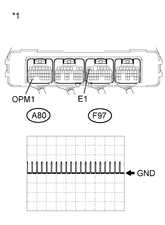
Text in Illustration *1 Component with harness connected
(Power Management Control ECU)
Connect an oscilloscope between the power management control ECU terminals specified in the table below, and measure the waveform.
Item Content Terminal A80-33 (OPM1) - F97-6 (E1) Equipment Setting 10 V/DIV., 20 ms./DIV. Condition Inspection mode
Power switch on (READY)
Result Result Proceed to Normal waveform A Waveform other than normal waveform for LHD B for RHD C No waveform (0 V) D No waveform (12 V) E -
Turn the power switch off.
B 
REPLACE POWER MANAGEMENT CONTROL ECU (for LHD) Click here
C
REPLACE POWER MANAGEMENT CONTROL ECU (for RHD) Click here
D 
CHECK HARNESS AND CONNECTOR (POWER MANAGEMENT CONTROL ECU - OIL PUMP WITH MOTOR ASSEMBLY) Click here
E
CHECK HARNESS AND CONNECTOR (POWER MANAGEMENT CONTROL ECU - OIL PUMP W/MOTOR ASSEMBLY) Click here
A 
REPLACE OIL PUMP WITH MOTOR ASSEMBLY Click here
-
-
CHECK HARNESS AND CONNECTOR (POWER MANAGEMENT CONTROL ECU - OIL PUMP WITH MOTOR ASSEMBLY)
-
Disconnect the A75 connector from the oil pump with motor assembly.
-
Disconnect the A80 connector from the power management control ECU.
-
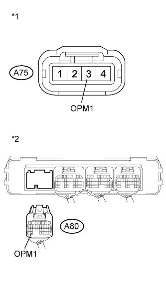
Text in Illustration *1 Front view of wire harness connector
(to Oil Pump with Motor Assembly)
*2 Rear view of wire harness connector
(to Power Management Control ECU)
Measure the resistance according to the value(s) in the table below.
Standard Resistance (Check for Open) Tester Connection Switch Condition Specified Condition A75-3 (OPM1) - A80-33 (OPM1) Power switch off Below 1 Ω Standard Resistance (Check for Short) Tester Connection Switch Condition Specified Condition A75-3 (OPM1) or A80-33 (OPM1) - Body ground and other terminals Power switch off 10 kΩ or higher -
Connect the power management control ECU connector.
-
Connect the oil pump with motor assembly connector.
NG
REPAIR OR REPLACE HARNESS OR CONNECTOR
OK 
-
-
INSPECT OIL PUMP WITH MOTOR ASSEMBLY
-
Disconnect the A80 and F97 connector from the power management control ECU.
-
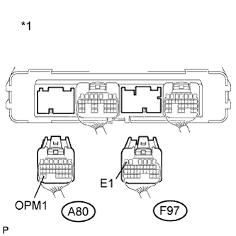
Text in Illustration *1 Rear view of wire harness connector
(to Power Management Control ECU)
Measure the resistance according to the value(s) in the table below.
Standard Resistance Tester Connection Switch Condition Specified Condition A80-33 (OPM1) - F97-6 (E1) Power switch off 10 kΩ or higher Result Result Proceed to OK (for LHD) A OK (for RHD) B NG C -
Connect the power management control ECU connector.
B
REPLACE POWER MANAGEMENT CONTROL ECU (for RHD) Click here
C
REPLACE OIL PUMP WITH MOTOR ASSEMBLY Click here
A
REPLACE POWER MANAGEMENT CONTROL ECU (for LHD) Click here
-
-
CHECK HARNESS AND CONNECTOR (POWER MANAGEMENT CONTROL ECU - OIL PUMP W/MOTOR ASSEMBLY)
-
Disconnect the A75 connector from the oil pump with motor assembly.
-
Disconnect the A80 connector from the power management control ECU.
-
Turn the power switch on (IG).
-
Text in Illustration *1 Front view of wire harness connector
(to Oil Pump with Motor Assembly)
*2 Rear view of wire harness connector
(to Power Management Control ECU)
Measure the voltage according to the value(s) in the table below.
Standard Voltage Tester Connection Condition Specified Condition A75-3 (OPM1) or A80-33 (OPM1) - Body ground Power switch on (IG) Below 1 V Note
Turning the power switch on (IG) with the power management control ECU connector disconnected causes other DTCs to be stored. Clear the DTCs after performing this inspection.
-
Turn the power switch off.
-
Connect the power management control ECU connector.
-
Connect the oil pump with motor assembly connector.
NG
REPAIR OR REPLACE HARNESS OR CONNECTOR
OK
-
-
INSPECT OIL PUMP WITH MOTOR ASSEMBLY
-
Disconnect the A75 connector from the oil pump with motor assembly.
-
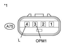
Text in Illustration *1 Component without harness connected
(Oil Pump with Motor Assembly)
Measure the resistance according to the value(s) in the table below.
Standard Resistance Tester Connection Switch Condition Specified Condition A75-3 (OPM1) - A75-4 (L) Power switch off 10 kΩ or higher Result Result Proceed to OK (for LHD) A OK (for RHD) B NG C -
Connect the oil pump with motor assembly connector.
B
REPLACE POWER MANAGEMENT CONTROL ECU (for RHD) Click here
C
REPLACE OIL PUMP WITH MOTOR ASSEMBLY Click here
A
REPLACE POWER MANAGEMENT CONTROL ECU (for LHD) Click here
-