HYBRID CONTROL SYSTEM, Diagnostic DTC:P2511-149

| DTC Code | DTC Name |
|---|---|
| P2511-149 | ECM/PCM Power Relay Sense Circuit Intermittent |
DESCRIPTION
This DTC indicates that the power management control ECU (HV CPU) monitors the +B power source voltage to detect an instantaneous interruption.
| DTC No. | INF Code | DTC Detection Condition | Trouble Area |
|---|---|---|---|
| P2511 | 149 | When the power switch is on (READY), the power management control ECU is reset. |
|
WIRING DIAGRAM
Refer to the wiring diagram for DTC P3110-223 Click here.
INSPECTION PROCEDURE
PROCEDURE
-
CHECK BATTERY TERMINAL (CONTACT PROBLEM)
-
Check the connection of the auxiliary battery terminal.
OK The terminal is connected securely and there is no contact problem.
NG 
CONNECT SECURELY
OK 
-
-
CHECK CONNECTOR CONNECTION CONDITION (POWER MANAGEMENT CONTROL ECU CONNECTOR)
-
Check the connections of the power management control ECU connectors.
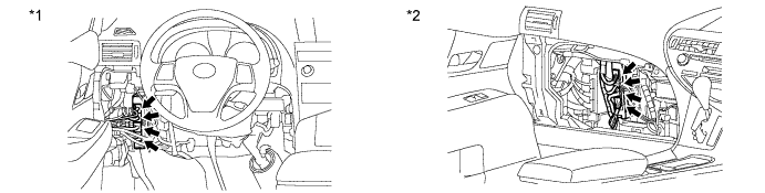
Text in Illustration *1 for LHD *2 for RHD OK The connectors are connected securely and there are no contact problems.
NG
CONNECT SECURELY
OK
-
-
CHECK HARNESS AND CONNECTOR (POWER MANAGEMENT CONTROL ECU - IGCT MAIN RELAY)
-
Remove the IGCT MAIN relay from the engine room relay block No. 2.
-
Disconnect connector A80 and A81 from power management control ECU.
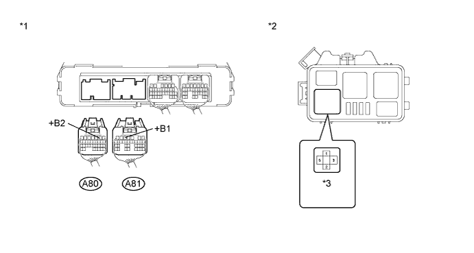
Text in Illustration *1 Rear view of wire harness connector
(to Power Management Control ECU)
*2 Engine Room Relay Block No. 2 *3 IGCT MAIN Relay - - -
Measure the resistance according to the value(s) in the table below.
Standard resistance Tester Connection Switch Condition Specified Condition A81-5 (+B1) - 3 (IGCT MAIN relay) Power switch off Below 1 Ω A80-2 (+B2) - 3 (IGCT MAIN relay) Power switch off Below 1 Ω -
Install the IGCT MAIN relay.
-
Connect the power management control ECU connector.
NG
REPAIR OR REPLACE HARNESS OR CONNECTOR
OK
-
-
CHECK FOR INTERMITTENT PROBLEMS
-
Check for intermittent problems Click here.
-
Check the connection and terminal contact pressure of connectors and wire harnesses between the power management control ECU and the engine room relay block No. 2.
-
When the power switch is on (READY), jiggle the connectors and wire harnesses between the power management control ECU and the engine room relay block No. 2.
Result Result Proceed to Problem symptom recurs. A Problem symptom does not recur. for LHD B for RHD C
-
B
REPLACE POWER MANAGEMENT CONTROL ECU (for LHD) Click here
C
REPLACE POWER MANAGEMENT CONTROL ECU (for RHD) Click here
A 
REPAIR OR REPLACE MALFUNCTIONING PARTS, COMPONENT AND AREA
-