HYBRID CONTROL SYSTEM, Diagnostic DTC:P0A79-716

| DTC Code | DTC Name |
|---|---|
| P0A79-716 | Drive Motor "B" Inverter Performance |
DESCRIPTION
For a description of the inverter, Click here.
Tech Tips
The term "drive motor B" indicates MGR.
| DTC No. | INF Code | DTC Detection Condition | Trouble Area |
|---|---|---|---|
| P0A79 | 716 | Malfunction (short circuit) in the rear motor inverter inside the inverter with converter assembly |
|
INSPECTION PROCEDURE
CAUTION:
-
Before inspecting the high-voltage system or disconnecting the low voltage connector of the inverter with converter assembly, take safety precautions such as wearing insulated gloves and removing the service plug grip to prevent electrical shocks. After removing the service plug grip, put it in your pocket to prevent other technicians from accidentally reconnecting it while you are working on the high-voltage system.
-
After disconnecting the service plug grip, wait for at least 10 minutes before touching any of the high-voltage connectors or terminals. After waiting for 10 minutes, check the voltage at the terminals in the inspection point in the inverter with converter assembly. The voltage should be 0 V before beginning work.
Note
-
DTC P0A79-716 is stored after any of DTCs P0A79-136, 692, 693, 694, 695, 696, 712, 812, 813 and 814 are stored. After troubleshooting and repairing DTC P0A79-716, be sure to troubleshoot all the other DTCs.
-
Depending on the conditions in which the vehicle is being operated when a short circuit occurs in the inverter with converter assembly, the No. 3 frame wire (rear motor cable), extension wire assembly, or rear traction motor with transaxle assembly may be affected. As this DTC is stored if a short circuit occurs in the inverter with converter assembly, perform a road test to check the No. 3 frame wire (rear motor cable), extension wire assembly, and rear traction motor with transaxle assembly. If problems are found, replace the malfunctioning parts.
-
After completing the repair, including repairing of previously output DTCs, drive the vehicle at a speed of approximately 40 km/h for 1 minute and check that DTC P0A91-705 (Drive Motor "B" Performance) is not output. If DTC P0A91-705 (Drive Motor "B" Performance) is output, replace the rear traction motor with transaxle assembly.
Tech Tips
Waiting for at least 10 minutes is required to discharge the high-voltage capacitor inside the inverter with converter assembly.
PROCEDURE
-
CHECK REAR TRACTION MOTOR WITH TRANSAXLE ASSEMBLY (MGR)
CAUTION:
Be sure to wear insulated gloves.
-
Check that the service plug grip is not installed.
Note
After removing the service plug grip, do not turn the power switch on (READY), unless instructed by the repair manual because this may cause a malfunction.
-
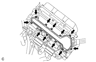
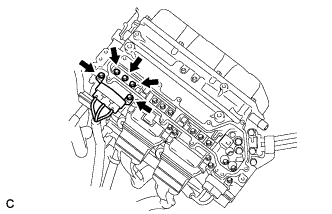
Remove the inverter terminal cover from the inverter with converter assembly.
-
Disconnect the rear motor cable from the inverter with converter assembly.
-
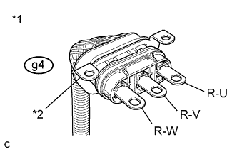
Text in Illustration *1 Rear Motor Cable *2 Shielded Ground Check MGR for an interphase short using a milliohmmeter.
-
Using a milliohmmeter, measure the resistance according to the value(s) in the table below.
Tech Tips
If the MGR temperature is high, the resistance will vary greatly from the specification. Therefore, measure the resistance at least 8 hours after the vehicle is stopped.
Standard Resistance Tester Connection Switch Condition Specified Condition g4-3 (R-U) - g4-2 (R-V) Power switch off 162 to 176 mΩ g4-2 (R-V) - g4-1 (R-W) Power switch off 162 to 176 mΩ g4-1 (R-W) - g4-3 (R-U) Power switch off 162 to 176 mΩ Tech Tips
To correct the variation of the measured resistance due to temperature, use the following formula to calculate the resistance at 20°C (68° F).
-
R20 = Rt / {1 + 0.00393 X (T - 20)}
The calculation is based on the following:
-
R20: Resistance at 20°C (68° F) (mΩ)
-
Rt: Measured resistance (mΩ)
-
T: Temperature when the resistance is measured (° C)
-
-
-
Using a megohmmeter set to 500 V, measure the resistance according to the value(s) in the table below.
Note
Be sure to set the megohmmeter to 500 V when performing this test. Using a setting higher than 500 V can result in damage to the component being inspected.
Standard resistance Tester Connection Switch Condition Specified Condition g4-3 (R-U) - Body ground and shielded ground Power switch off 100 MΩ or higher g4-2 (R-V) - Body ground and shielded ground Power switch off 100 MΩ or higher g4-1 (R-W) - Body ground and shielded ground Power switch off 100 MΩ or higher -
Connect the rear motor cable.
-
Install the inverter terminal cover.
NG 
OK 
-
-
REPLACE INVERTER WITH CONVERTER ASSEMBLY
-
Replace the inverter with converter assembly Click here.
NEXT
CHECK DTC OUTPUT Click here
-
-
CHECK NO.3 WIRE FRAME (REAR MOTOR CABLE)
CAUTION:
Be sure to wear insulated gloves.
-
Check that the service plug grip is not installed.
Note
After removing the service plug grip, do not turn the power switch on (READY), unless instructed by the repair manual because this may cause a malfunction.
-
Remove the inverter terminal cover from the inverter with converter assembly.
-
Disconnect the rear motor cable from the inverter with converter assembly.
-
Disconnect the rear motor cable from the rear traction motor with transaxle assembly.
-
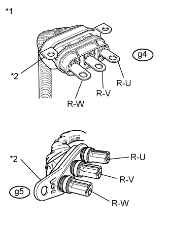
Text in Illustration *1 Rear Motor Cable *2 Shielded Ground Using a megohmmeter set to 500 V, measure the resistance according to the value(s) in the table below.
Note
Be sure to set the megohmmeter to 500 V when performing this test. Using a setting higher than 500 V can result in damage to the component being inspected.
Standard Resistance Tester Connection Switch Condition Specified Condition g4-3 (R-U) - Body ground and shielded ground Power switch off 10 MΩ or higher g4-2 (R-V) - Body ground and shielded ground Power switch off 10 MΩ or higher g4-1 (R-W) - Body ground and shielded ground Power switch off 10 MΩ or higher Note
Wrap the terminals of three-phase AC cable with insulating tape to avoid them coming into contact with body ground.
-
Measure the resistance according to the value(s) in the table below.
Standard Resistance Tester Connection Switch Condition Specified Condition g4-3 (R-U) - g5-3 (R-U) Power switch off Below 1 Ω g4-2 (R-V) - g5-2 (R-V) Power switch off Below 1 Ω g4-1 (R-W) - g5-1 (R-W) Power switch off Below 1 Ω g4-3 (R-U) - g5-2 (R-V) Power switch off 10 kΩ or higher g4-2 (R-V) - g5-1 (R-W) Power switch off 10 kΩ or higher g4-1 (R-W) - g5-3 (R-U) Power switch off 10 kΩ or higher -
Connect the rear motor cable to the rear traction motor with transaxle assembly.
-
Connect the rear motor cable to the inverter with converter assembly.
-
Install the inverter terminal cover.
NG
OK
-
-
CHECK EXTENSION WIRE ASSEMBLY
CAUTION:
Be sure to wear insulated gloves.
-
Check that the service plug grip is not installed.
Note
After removing the service plug grip, do not turn the power switch on (READY), unless instructed by the repair manual because this may cause a malfunction.
-
Remove the rear traction motor with transaxle assembly.
-
Remove the extension wire assembly from the rear traction motor with transaxle assembly.
-
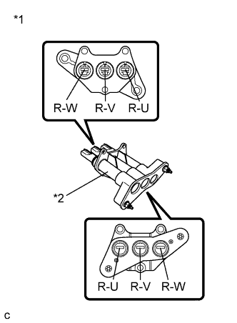
Text in Illustration *1 Extension Wire Assembly *2 Shielded Ground Using a megohmmeter set to 500 V, measure the resistance according to the value(s) in the table below.
Note
Be sure to set the megohmmeter to 500 V when performing this test. Using a setting higher than 500 V can result in damage to the component being inspected.
Standard Resistance Tester Connection Switch Condition Specified Condition R-U - Body ground and shielded ground Power switch off 10 MΩ or higher R-V - Body ground and shielded ground Power switch off 10 MΩ or higher R-W - Body ground and shielded ground Power switch off 10 MΩ or higher -
Measure the resistance according to the value(s) in the table below.
Standard Resistance Tester Connection Switch Condition Specified Condition R-U - R-U Power switch off Below 1 Ω R-V - R-V Power switch off Below 1 Ω R-W - R-W Power switch off Below 1 Ω R-U - R-V Power switch off 10 kΩ or higher R-V - R-W Power switch off 10 kΩ or higher R-W - R-U Power switch off 10 kΩ or higher -
Install the extension wire.
-
Install the rear traction motor with transaxle assembly.
NG
CHECK REAR TRACTION MOTOR WITH TRANSAXLE ASSEMBLY (MGR) Click here
OK
-
-
REPLACE REAR TRACTION MOTOR WITH TRANSAXLE ASSEMBLY
-
Replace the rear traction motor with transaxle assembly Click here.
NEXT
REPLACE INVERTER WITH CONVERTER ASSEMBLY Click here
-
-
CHECK REAR TRACTION MOTOR WITH TRANSAXLE ASSEMBLY (MGR)
CAUTION:
Be sure to wear insulated gloves.
-
Check that the service plug grip is not installed.
-
Remove the No. 3 wire frame and extension wire assembly from the rear traction motor with transaxle assembly.
-
Check MGR for an interphase short using a milliohmmeter.
-
Using a milliohmmeter, measure the resistance according to the value(s) in the table below.
Tech Tips
If the MGR temperature is high, the resistance will vary greatly from the specification. Therefore, measure the resistance at least 8 hours after the vehicle is stopped.
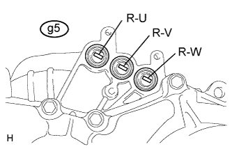
Standard Resistance Tester Connection Switch Condition Specified Condition g5-3 (R-U) - g5-2 (R-V) Power switch off 142 to 152 mΩ g5-2 (R-V) - g5-1 (R-W) Power switch off 142 to 152 mΩ g5-1 (R-W) - g5-3 (R-U) Power switch off 142 to 152 mΩ Tech Tips
-
To correct the variation of the measured resistance due to temperature, use the following formula to calculate the resistance at 20°C (68°F).
-
R20 = Rt / {1 + 0.00393 X (T - 20)}
-
The calculation is based on the following:
-
R20: Resistance at 20°C (68°F) (mΩ)
-
Rt: Measured resistance (mΩ)
-
T: Temperature when the resistance is measured (°C)
-
-
-
Using a megohmmeter set to 500 V, measure the resistance according to the value(s) in the table below.
Note
Be sure to set the megohmmeter to 500 V when performing this test. Using a setting higher than 500 V can result in damage to the component being inspected.
Standard Resistance Tester Connection Switch Condition Specified Condition g5-3 (R-U) - Body ground and shielded wire ground Power switch off 100 MΩ or higher g5-2 (R-V) - Body ground and shielded wire ground Power switch off 100 MΩ or higher g5-1 (R-W) - Body ground and shielded wire ground Power switch off 100 MΩ or higher -
Install the No. 3 wire frame and extension wire assembly to the rear traction motor with transaxle assembly.
NG
REPLACE REAR TRACTION MOTOR WITH TRANSAXLE ASSEMBLY Click here
OK
-
-
REPLACE EXTENSION WIRE ASSEMBLY
-
Replace the extension wire assembly Click here.
NEXT
REPLACE INVERTER WITH CONVERTER ASSEMBLY Click here
-
-
REPLACE REAR TRACTION MOTOR WITH TRANSAXLE ASSEMBLY
-
Replace the rear traction motor with transaxle assembly Click here.
NEXT
-
-
REPLACE EXTENSION WIRE ASSEMBLY
-
Replace the extension wire assembly Click here.
NEXT
REPLACE INVERTER WITH CONVERTER ASSEMBLY Click here
-
-
CHECK EXTENSION WIRE ASSEMBLY
CAUTION:
Be sure to wear insulated gloves.
-
Check that the service plug grip is not installed.
Note
After removing the service plug grip, do not turn the power switch on (READY), unless instructed by the repair manual because this may cause a malfunction.
-
Remove the rear traction motor with transaxle assembly.
-
Remove the extension wire assembly from the rear traction motor with transaxle assembly.
-
Text in Illustration *1 Extension Wire Assembly *2 Shielded Ground Using a megohmmeter set to 500 V, measure the resistance according to the value(s) in the table below.
Note
Be sure to set the megohmmeter to 500 V when performing this test. Using a setting higher than 500 V can result in damage to the component being inspected.
Standard Resistance Tester Connection Switch Condition Specified Condition R-U - Body ground and shielded ground Power switch off 10 MΩ or higher R-V - Body ground and shielded ground Power switch off 10 MΩ or higher R-W - Body ground and shielded ground Power switch off 10 MΩ or higher -
Measure the resistance according to the value(s) in the table below.
Standard Resistance Tester Connection Switch Condition Specified Condition R-U - R-U Power switch off Below 1 Ω R-V - R-V Power switch off Below 1 Ω R-W - R-W Power switch off Below 1 Ω R-U - R-V Power switch off 10 kΩ or higher R-V - R-W Power switch off 10 kΩ or higher R-W - R-U Power switch off 10 kΩ or higher -
Install the extension wire.
-
Install the rear traction motor with transaxle assembly.
NG
CHECK REAR TRACTION MOTOR WITH TRANSAXLE ASSEMBLY (MGR) Click here
OK
-
-
CHECK REAR TRACTION MOTOR WITH TRANSAXLE ASSEMBLY (MGR)
CAUTION:
Be sure to wear insulated gloves.
-
Check that the service plug grip is not installed.
-
Remove the No. 3 wire frame and extension wire assembly from the rear traction motor with transaxle assembly.
-
Check MGR for an interphase short using a milliohmmeter.
-
Using a milliohmmeter, measure the resistance according to the value(s) in the table below.
Tech Tips
If the MGR temperature is high, the resistance will vary greatly from the specification. Therefore, measure the resistance at least 8 hours after the vehicle is stopped.
Standard Resistance Tester Connection Switch Condition Specified Condition g5-3 (R-U) - g5-2 (R-V) Power switch off 142 to 152 mΩ g5-2 (R-V) - g5-1 (R-W) Power switch off 142 to 152 mΩ g5-1 (R-W) - g5-3 (R-U) Power switch off 142 to 152 mΩ Tech Tips
-
To correct the variation of the measured resistance due to temperature, use the following formula to calculate the resistance at 20°C (68°F).
-
R20 = Rt / {1 + 0.00393 X (T - 20)}
-
The calculation is based on the following:
-
R20: Resistance at 20°C (68°F) (mΩ)
-
Rt: Measured resistance (mΩ)
-
T: Temperature when the resistance is measured (°C)
-
-
-
Using a megohmmeter set to 500 V, measure the resistance according to the value(s) in the table below.
Note
Be sure to set the megohmmeter to 500 V when performing this test. Using a setting higher than 500 V can result in damage to the component being inspected.
Standard Resistance Tester Connection Switch Condition Specified Condition g5-3 (R-U) - Body ground and shielded wire ground Power switch off 100 MΩ or higher g5-2 (R-V) - Body ground and shielded wire ground Power switch off 100 MΩ or higher g5-1 (R-W) - Body ground and shielded wire ground Power switch off 100 MΩ or higher -
Install the No. 3 wire frame and extension wire assembly to the rear traction motor with transaxle assembly.
NG
REPLACE REAR TRACTION MOTOR WITH TRANSAXLE ASSEMBLY Click here
OK
-
-
REPLACE NO.3 WIRE FRAME
-
Replace the No. 3 wire frame Click here.
NEXT
REPLACE INVERTER WITH CONVERTER ASSEMBLY Click here
-
-
CHECK REAR TRACTION MOTOR WITH TRANSAXLE ASSEMBLY (MGR)
CAUTION:
Be sure to wear insulated gloves.
-
Check that the service plug grip is not installed.
-
Remove the No. 3 wire frame and extension wire assembly from the rear traction motor with transaxle assembly.
-
Check MGR for an interphase short using a milliohmmeter.
-
Using a milliohmmeter, measure the resistance according to the value(s) in the table below.
Tech Tips
If the MGR temperature is high, the resistance will vary greatly from the specification. Therefore, measure the resistance at least 8 hours after the vehicle is stopped.
Standard Resistance Tester Connection Switch Condition Specified Condition g5-3 (R-U) - g5-2 (R-V) Power switch off 142 to 152 mΩ g5-2 (R-V) - g5-1 (R-W) Power switch off 142 to 152 mΩ g5-1 (R-W) - g5-3 (R-U) Power switch off 142 to 152 mΩ Tech Tips
-
To correct the variation of the measured resistance due to temperature, use the following formula to calculate the resistance at 20°C (68°F).
-
R20 = Rt / {1 + 0.00393 X (T - 20)}
-
The calculation is based on the following:
-
R20: Resistance at 20°C (68°F) (mΩ)
-
Rt: Measured resistance (mΩ)
-
T: Temperature when the resistance is measured (°C)
-
-
-
Using a megohmmeter set to 500 V, measure the resistance according to the value(s) in the table below.
Note
Be sure to set the megohmmeter to 500 V when performing this test. Using a setting higher than 500 V can result in damage to the component being inspected.
Standard Resistance Tester Connection Switch Condition Specified Condition g5-3 (R-U) - Body ground and shielded wire ground Power switch off 100 MΩ or higher g5-2 (R-V) - Body ground and shielded wire ground Power switch off 100 MΩ or higher g5-1 (R-W) - Body ground and shielded wire ground Power switch off 100 MΩ or higher -
Install the No. 3 wire frame and extension wire assembly to the rear traction motor with transaxle assembly.
NG
REPLACE REAR TRACTION MOTOR WITH TRANSAXLE ASSEMBLY Click here
OK
-
-
REPLACE EXTENSION WIRE ASSEMBLY
-
Replace the extension wire assembly Click here.
NEXT
REPLACE NO.3 WIRE FRAME Click here
-
-
REPLACE REAR TRACTION MOTOR WITH TRANSAXLE ASSEMBLY
-
Replace the rear traction motor with transaxle assembly Click here.
NEXT
-
-
REPLACE EXTENSION WIRE ASSEMBLY
-
Replace the extension wire assembly Click here.
NEXT
REPLACE NO.3 WIRE FRAME Click here
-
-
REPLACE REAR TRACTION MOTOR WITH TRANSAXLE ASSEMBLY
-
Replace the rear traction motor with transaxle assembly Click here.
NEXT
-
-
REPLACE NO.3 WIRE FRAME
-
Replace the No. 3 wire frame Click here.
NEXT
-
-
REPLACE INVERTER WITH CONVERTER ASSEMBLY
-
Replace the inverter with converter assembly Click here.
NEXT
-
-
CHECK DTC OUTPUT
-
Check the other DTCs that were output together with DTC P0A79-716.
Result DTC No. Relevant Diagnosis P0A79-136, 692, 693, 694, 695, 696, 712, 812, 813, 814 Drive Motor "B" Inverter Performance Note
DTC P0A79-716 is stored after any of DTCs P0A79-136, 692, 693, 694, 695, 696, 712, 812, 813 and 814 are stored. After troubleshooting and repairing DTC P0A79-716, be sure to troubleshoot all the other DTCs.
NEXT 
GO TO DTC CHART Click here
-