HYBRID CONTROL SYSTEM, Diagnostic DTC:P0A55-687

| DTC Code | DTC Name |
|---|---|
| P0A55-687 | Drive Motor "B" Current Sensor Circuit |
DESCRIPTION
The MG ECU located in the inverter with converter assembly monitors its internal operation and it will set DTCs when it detects malfunctions.
| DTC No. | INF Code | DTC Detection Condition | Trouble Area |
|---|---|---|---|
| P0A55 | 687 | Motor current sensor high resolution circuit signal is out of range or there is a difference between it and the motor current sensor low resolution circuit current value. | Inverter with converter assembly |
INSPECTION PROCEDURE
PROCEDURE
-
CHECK DTC OUTPUT
-
Connect the intelligent tester to the DLC3.
-
Turn the power switch on (IG).
-
Enter the following menus: Powertrain / Hybrid Control / Trouble Codes.
-
Check if DTCs are output.
Result Result Proceed to P0A55-687 only is output. A Any of the following DTCs are also output. B DTC No. Relevant Diagnosis P0A51-174 Drive Motor "A" Current Sensor Circuit P0A69 (all INF codes)*1 Drive Motor "B" Phase V Current P0A6C (all INF codes)*1 Drive Motor "B" Phase W Current P0A79-693, 694, 695, 712 Drive Motor "B" Inverter Performance Tech Tips
-
*1: If any INF codes are output for this DTC, refer to the corresponding diagnostic procedure.
-
P0A55-687 may be output due to a malfunction which causes the DTCs in the table above to be output. In this case, first troubleshoot the output DTCs in the table above. Then, perform a reproduction test to check that no DTCs are output.
-
-
Turn the power switch off.
B 
GO TO DTC CHART Click here
A 
-
-
CHECK CONNECTOR CONNECTION CONDITION (INVERTER WITH CONVERTER ASSEMBLY CONNECTOR)
CAUTION:
Be sure to wear insulated gloves.
-
Check that the service plug grip is not installed.
Note
After removing the service plug grip, do not turn the power switch on (READY), unless instructed by the repair manual because this may cause a malfunction.
Note
Before disconnecting the connector, confirm that it is properly connected by checking that the locking claws are engaged and that the connector does not pull out.
-
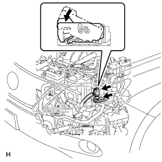
Check the connection of the low voltage connector of the inverter with converter assembly.
OK The connector is connected securely and there are no contact problems. Tech Tips
When connecting the connector, insert it with the locking lever in the raised position. Rotate the lever downward and make sure that the connector is pulled into its socket. When the locking lever is in its fully closed position, a click will be heard as its locking claws engage. After the click is heard, pull up on the connector to confirm that it is properly connected.
NG
CONNECT SECURELY
OK 
REPLACE INVERTER WITH CONVERTER ASSEMBLY Click here
-