HYBRID CONTROL SYSTEM, Diagnostic DTC:P0A4B-253, P0A4C-513, P0A4D-255

| DTC Code | DTC Name |
|---|---|
| P0A4B-253 | Generator Position Sensor Circuit |
| P0A4C-513 | Generator Position Sensor Circuit Range / Performance |
| P0A4D-255 | Generator Position Sensor Circuit Low |
DESCRIPTION
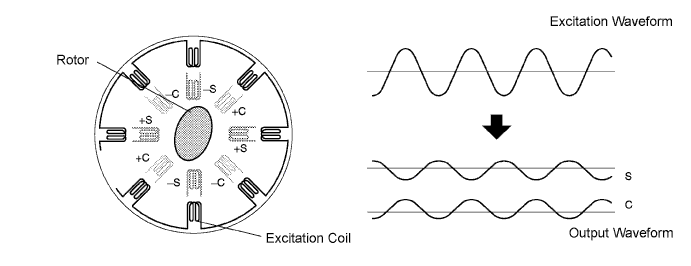
A resolver is a sensor that is used to detect the position of the magnetic poles the rotor of a motor generator. Knowing the position of the poles is indispensable for ensuring precise control of MG2 and MG1.
Each resolver contains a stator that has an excitation coil and 2 detection coils (S, C). The gap between the stator and rotor changes as the rotor turns because the rotor is oval shaped. An alternating current with a predetermined frequency flows through the excitation coil, and detection coils S and C output alternating currents in accordance with the sensor rotor position.
The inverter with converter assembly (MG ECU) detects the absolute position of the rotor according to the phases of detection coils S and C and the heights of their waveforms. Furthermore, the CPU calculates the amount of change in the position within a predetermined length of time, in order to use the resolver as a speed sensor.
The MG ECU monitors signals output from the motor resolver and detects malfunctions.
| DTC No. | INF Code | DTC Detection Condition | Trouble Area |
|---|---|---|---|
| P0A4B | 253 | Interphase short in the generator resolver circuit |
|
| P0A4C | 513 | Generator resolver output is out of the normal range | |
| P0A4D | 255 | Open or short in the generator resolver circuit |
WIRING DIAGRAM
Refer to the wiring diagram for DTC P0A1A-200 Click here.
INSPECTION PROCEDURE
CAUTION:
-
Before inspecting the high-voltage system or disconnecting the low voltage connector of the inverter with converter assembly, take safety precautions such as wearing insulated gloves and removing the service plug grip to prevent electrical shocks. After removing the service plug grip, put it in your pocket to prevent other technicians from accidentally reconnecting it while you are working on the high-voltage system.
-
After disconnecting the service plug grip, wait for at least 10 minutes before touching any of the high-voltage connectors or terminals. After waiting for 10 minutes, check the voltage at the terminals in the inspection point in the inverter with converter assembly. The voltage should be 0 V before beginning work.
Tech Tips
Waiting for at least 10 minutes is required to discharge the high-voltage capacitor inside the inverter with converter assembly.
Note
Check for output DTCs again after the repair has been completed. If P0A78-286, P0A7A-324, or P0A79-696 is output, replace the inverter with converter assembly.
Tech Tips
-
If the problem symptom cannot be reproduced, performing a road test on a road on which the vehicle tends to vibrate will make it easier to reproduce the symptom.
-
After repair, confirm that no DTCs are output by performing DTC Output Confirmation Operation Click here.
PROCEDURE
-
CHECK CONNECTOR CONNECTION CONDITION (INVERTER WITH CONVERTER ASSEMBLY CONNECTOR)
CAUTION:
Be sure to wear insulated gloves.
-
Check that the service plug grip is not installed.
Note
After removing the service plug grip, do not turn the power switch on (READY), unless instructed by the repair manual because this may cause a malfunction.
Note
Before disconnecting the connector, confirm that it is properly connected by checking that the locking claws are engaged and that the connector does not pull out.
-
Check the connection of the low voltage connector of the inverter with converter assembly.
OK The connector is connected securely and there are no contact problems. Tech Tips
When connecting the connector, insert it with the locking lever in the raised position. Rotate the lever downward and make sure that the connector is pulled into its socket. When the locking lever is in its fully closed position, a click will be heard as its locking claws engage. After the click is heard, pull up on the connector to confirm that it is properly connected.
NG 
CONNECT SECURELY
OK 
-
-
CHECK HARNESS AND CONNECTOR (INVERTER WITH CONVERTER ASSEMBLY - GENERATOR RESOLVER)
CAUTION:
Be sure to wear insulated gloves.
-
Disconnect the low voltage connector D44 from the inverter with converter assembly.
-
Turn the power switch on (IG).
-
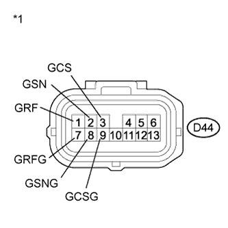
Text in Illustration *1 Front view of wire harness connector
(to Inverter with Converter Assembly)
Measure the voltage according to the value(s) in the table below.
Standard Voltage Tester Connection Switch Condition Specified Condition D44-1 (GRF) - Body ground Power switch on (IG) Below 1 V D44-7 (GRFG) - Body ground Power switch on (IG) Below 1 V D44-2 (GSN) - Body ground Power switch on (IG) Below 1 V D44-8 (GSNG) - Body ground Power switch on (IG) Below 1 V D44-3 (GCS) - Body ground Power switch on (IG) Below 1 V D44-9 (GCSG) - Body ground Power switch on (IG) Below 1 V Note
Turning the power switch on (IG) with the low voltage connector of the inverter with converter assembly disconnected causes other DTCs to be stored. Clear the DTCs after performing this inspection.
-
Turn the power switch off.
-
Connect the low voltage connector from the inverter with converter assembly.
NG
REPAIR OR REPLACE HARNESS OR CONNECTOR
OK
-
-
CHECK GENERATOR RESOLVER
-
Disconnect the low voltage connector D44 from the inverter with converter assembly.
-
Text in Illustration *1 Front view of wire harness connector
(to Inverter with Converter Assembly)
Measure the resistance according to the value(s) in the table below.
Standard Resistance (Check for Open) Tester Connection Switch Condition Specified Condition D44-1 (GRF) - D44-7 (GRFG) Power switch off 4.2 to 12.5 Ω D44-2 (GSN) - D44-8 (GSNG) Power switch off 9.8 to 20.1Ω D44-3 (GCS) - D44-9 (GCSG) Power switch off 9.8 to 20.1 Ω Standard Resistance (Check for Short) Tester Connection Switch Condition Specified Condition D44-1 (GRF) or D44-7 (GRFG) - Body ground and other terminals Power switch off 10 kΩ or higher D44-2 (GSN) or D44-8 (GSNG) - Body ground and other terminals Power switch off 10 kΩ or higher D44-3 (GCS) or D44-9 (GCSG) - Body ground and other terminals Power switch off 10 kΩ or higher -
Connect the inverter with converter assembly connector.
NG 
OK
-
-
CHECK HARNESS AND CONNECTOR (INVERTER WITH CONVERTER ASSEMBLY - MOTOR RESOLVER)
CAUTION:
Be sure to wear insulated gloves.
-
Disconnect the low voltage connector D44 from the inverter with converter assembly.
-
Turn the power switch on (IG).
-
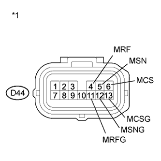
Text in Illustration *1 Front view of wire harness connector
(to Inverter with Converter Assembly)
Measure the voltage according to the value(s) in the table below.
Standard Voltage Tester Connection Switch Condition Specified Condition D44-4 (MRF) - Body ground Power switch on (IG) Below 1 V D44-11 (MRFG) - Body ground Power switch on (IG) Below 1 V D44-5 (MSN) - Body ground Power switch on (IG) Below 1 V D44-12 (MSNG) - Body ground Power switch on (IG) Below 1 V D44-6 (MCS) - Body ground Power switch on (IG) Below 1 V D44-13 (MCSG) - Body ground Power switch on (IG) Below 1 V Note
Turning the power switch on (IG) with the low voltage connector of the inverter with converter assembly disconnected causes other DTCs to be stored. Clear the DTCs after performing this inspection.
-
Turn the power switch off.
-
Connect the inverter with converter assembly connector.
NG
REPAIR OR REPLACE HARNESS OR CONNECTOR
OK
-
-
CHECK MOTOR RESOLVER
-
Disconnect the low voltage connector D44 from the inverter with converter assembly.
-
Text in Illustration *1 Front view of wire harness connector
(to Inverter with Converter Assembly)
Measure the resistance according to the value(s) in the table below.
Standard Resistance (Check for Open) Tester Connection Switch Condition Specified Condition D44-4 (MRF) - D44-11 (MRFG) Power switch off 4.2 to 12.5 Ω D44-5 (MSN) - D44-12 (MSNG) Power switch off 9.8 to 20.1 Ω D44-6 (MCS) - D44-13 (MCSG) Power switch off 9.8 to 20.1 Ω Standard Resistance (Check for Short) Tester Connection Switch Condition Specified Condition D44-4 (MRF) or D44-11 (MRFG) - Body ground and other terminals Power switch off 10 kΩ or higher D44-5 (MSN) or D44-12 (MSNG) - Body ground and other terminals Power switch off 10 kΩ or higher D44-6 (MCS) or D44-13 (MCSG) - Body ground and other terminals Power switch off 10 kΩ or higher -
Connect the inverter with converter assembly connector.
NG
OK
-
-
CHECK HARNESS AND CONNECTOR (INVERTER WITH CONVERTER ASSEMBLY - REAR MOTOR RESOLVER)
CAUTION:
Be sure to wear insulated gloves.
-
Disconnect the low voltage connector A79 from the inverter with converter assembly.
-
Turn the power switch on (IG).
-
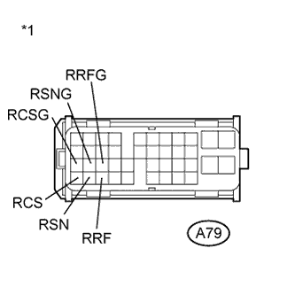
Text in Illustration *1 Front view of wire harness connector
(to Inverter with Converter Assembly)
Measure the voltage according to the value(s) in the table below.
Standard Voltage Tester Connection Switch Condition Specified Condition A79-34 (RRF) - Body ground Power switch on (IG) Below 1 V A79-23 (RRFG) - Body ground Power switch on (IG) Below 1 V A79-33 (RSN) - Body ground Power switch on (IG) Below 1 V A79-22 (RSNG) - Body ground Power switch on (IG) Below 1 V A79-32 (RCS) - Body ground Power switch on (IG) Below 1 V A79-21 (RCSG) - Body ground Power switch on (IG) Below 1 V Note
Turning the power switch on (IG) with the low voltage connector of the inverter with converter assembly disconnected causes other DTCs to be stored. Clear the DTCs after performing this inspection.
-
Turn the power switch off.
-
Connect the inverter with converter assembly connector.
NG
REPAIR OR REPLACE HARNESS OR CONNECTOR
OK
-
-
CHECK REAR MOTOR RESOLVER
-
Disconnect the low voltage connector A79 from the inverter with converter assembly.
-
Text in Illustration *1 Front view of wire harness connector
(to Inverter with Converter Assembly)
Measure the resistance according to the value(s) in the table below.
Standard Resistance (Check for Open) Tester Connection Switch Condition Specified Condition A79-34 (RRF) - A79-23 (RRFG) Power switch off 4.2 to 12.5 Ω A79-33 (RSN) - A79-22 (RSNG) Power switch off 9.8 to 20.1 Ω A79-32 (RCS) - A79-21 (RCSG) Power switch off 9.8 to 20.1 Ω Standard Resistance (Check for Short) Tester Connection Switch Condition Specified Condition A79-34 (RRF) or A79-23 (RRFG) - Body ground and other terminals Power switch off 10 kΩ or higher A79-33 (RSN) or A79-22 (RSNG) - Body ground and other terminals Power switch off 10 kΩ or higher A79-32 (RCS) or A79-21 (RCSG) - Body ground and other terminals Power switch off 10 kΩ or higher -
Connect the inverter with converter assembly connector.
NG
OK
-
-
CHECK CONNECTOR CONNECTION CONDITION (GENERATOR RESOLVER CONNECTOR)
-
Check the connection of the generator resolver connector.
OK The connector is connected securely and there are no contact problems.
NG
CONNECT SECURELY
OK
-
-
CHECK CONNECTOR CONNECTION CONDITION (MOTOR RESOLVER CONNECTOR)
-
Check the connection of the motor resolver connector.
OK The connector is connected securely and there are no contact problems.
NG
CONNECT SECURELY
OK
-
-
CHECK CONNECTOR CONNECTION CONDITION (REAR MOTOR RESOLVER CONNECTOR)
-
Check the connection of the rear motor resolver connector.
OK The connector is connected securely and there are no contact problems.
NG
CONNECT SECURELY
OK 
REFER TO REPLACE INVERTER WITH CONVERTER ASSEMBLY PARTS Click here
-
-
CHECK CONNECTOR CONNECTION CONDITION (GENERATOR RESOLVER CONNECTOR)
-
Check the connection of the generator resolver connector.
OK The connector is connected securely and there are no contact problems.
NG
CONNECT SECURELY
OK
-
-
CHECK HARNESS AND CONNECTOR (INVERTER WITH CONVERTER ASSEMBLY - GENERATOR RESOLVER)
-
Disconnect the low voltage connector D44 from the inverter with converter assembly.
-
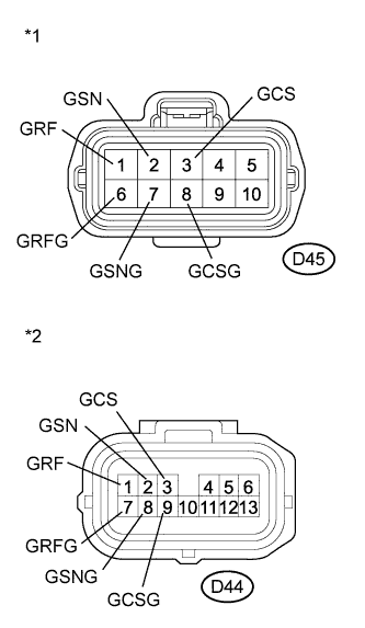
Text in Illustration *1 Front view of wire harness connector
(to Generator Resolver)
*2 Front view of wire harness connector
(to Inverter with Converter Assembly)
Disconnect the generator resolver connector.
-
Measure the resistance according to the value(s) in the table below.
Standard Resistance (Check for Open) Tester Connection Switch Condition Specified Condition D45-1 (GRF) - D44-1 (GRF) Power switch off Below 1 Ω D45-6 (GRFG) - D44-7 (GRFG) Power switch off Below 1 Ω D45-2 (GSN) - D44-2 (GSN) Power switch off Below 1 Ω D45-7 (GSNG) - D44-8 (GSNG) Power switch off Below 1 Ω D45-3 (GCS) - D44-3 (GCS) Power switch off Below 1 Ω D45-8 (GCSG) - D44-9 (GCSG) Power switch off Below 1 Ω Standard Resistance (Check for Short) Tester Connection Switch Condition Specified Condition D45-1 (GRF) or D44-1 (GRF) - Body ground and other terminals Power switch off 10 kΩ or higher D45-6 (GRFG) or D44-7 (GRFG) - Body ground and other terminals Power switch off 10 kΩ or higher D45-2 (GSN) or D44-2 (GSN) - Body ground and other terminals Power switch off 10 kΩ or higher D45-7 (GSNG) or D44-8 (GSNG) - Body ground and other terminals Power switch off 10 kΩ or higher D45-3 (GCS) or D44-3 (GCS) - Body ground and other terminals Power switch off 10 kΩ or higher D45-8 (GCSG) or D44-9 (GCSG) - Body ground and other terminals Power switch off 10 kΩ or higher Tech Tips
The generator resolver is not available separately. If it requires replacement, replace the hybrid vehicle transaxle assembly.
-
Connect the generator resolver connector.
-
Connect the inverter with converter assembly connector.
NG
REPAIR OR REPLACE HARNESS OR CONNECTOR
OK
REPLACE HYBRID VEHICLE GENERATOR ASSEMBLY Click here
-
-
CHECK CONNECTOR CONNECTION CONDITION (MOTOR RESOLVER CONNECTOR)
-
Check the connection of the motor resolver connector.
OK The connector is connected securely and there are no contact problems.
NG
CONNECT SECURELY
OK
-
-
CHECK HARNESS AND CONNECTOR (INVERTER WITH CONVERTER ASSEMBLY - MOTOR RESOLVER)
-
Disconnect the low voltage connector D44 from the inverter with converter assembly.
-
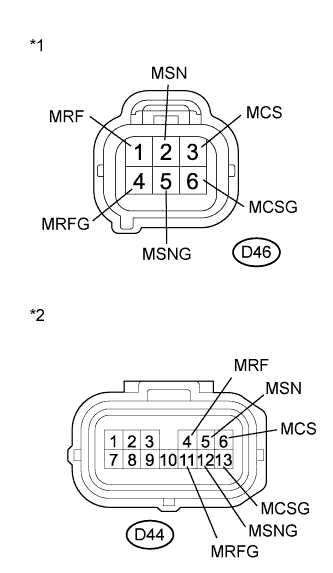
Text in Illustration *1 Front view of wire harness connector
(to Motor Resolver)
*2 Front view of wire harness connector
(to Inverter with Converter Assembly)
Disconnect the motor resolver connector.
-
Measure the resistance according to the value(s) in the table below.
Standard Resistance (Check for Open) Tester Connection Switch Condition Specified Condition D46-1 (MRF) - D44-4 (MRF) Power switch off Below 1 Ω D46-4 (MRFG) - D44-11 (MRFG) Power switch off Below 1 Ω D46-2 (MSN) - D44-5 (MSN) Power switch off Below 1 Ω D46-5 (MSNG) - D44-12 (MSNG) Power switch off Below 1 Ω D46-3 (MCS) - D44-6 (MCS) Power switch off Below 1 Ω D46-6 (MCSG) - D44-13 (MCSG) Power switch off Below 1 Ω Standard Resistance (Check for Short) Tester Connection Switch Condition Specified Condition D46-1 (MRF) or D44-4 (MRF) - Body ground and other terminals Power switch off 10 kΩ or higher D46-4 (MRFG) or D44-11 (MRFG) - Body ground and other terminals Power switch off 10 kΩ or higher D46-2 (MSN) or D44-5 (MSN) - Body ground and other terminals Power switch off 10 kΩ or higher D46-5 (MSNG) or D44-12 (MSNG) - Body ground and other terminals Power switch off 10 kΩ or higher D46-3 (MCS) or D44-6 (MCS) - Body ground and other terminals Power switch off 10 kΩ or higher D46-6 (MCSG) or D44-13 (MCSG) - Body ground and other terminals Power switch off 10 kΩ or higher Tech Tips
The motor resolver is not available separately. If it requires replacement, replace the hybrid vehicle transaxle assembly.
-
Connect the motor resolver connector.
-
Connect the inverter with converter assembly connector.
NG
REPAIR OR REPLACE HARNESS OR CONNECTOR
OK
REPLACE HYBRID VEHICLE TRANSAXLE ASSEMBLY Click here
-
-
CHECK CONNECTOR CONNECTION CONDITION (REAR MOTOR RESOLVER CONNECTOR)
-
Check the connection of the rear motor resolver connector.
OK The connector is connected securely and there are no contact problems.
NG
CONNECT SECURELY
OK
-
-
CHECK HARNESS AND CONNECTOR (INVERTER WITH CONVERTER ASSEMBLY - REAR MOTOR RESOLVER)
-
Disconnect the low voltage connector A79 from the inverter with converter assembly.
-
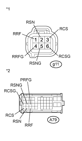
Text in Illustration *1 Front view of wire harness connector
(to Rear Motor Resolver)
*2 Front view of wire harness connector
(to Inverter with Converter Assembly)
Disconnect the rear motor resolver connector.
-
Measure the resistance according to the value(s) in the table below.
Standard Resistance (Check for Open) Tester Connection Switch Condition Specified Condition g11-1 (RRF) - A79-34 (RRF) Power switch off Below 1 Ω g11-4 (RRFG) - A79-23 (RRFG) Power switch off Below 1 Ω g11-2 (RSN) - A79-33 (RSN) Power switch off Below 1 Ω g11-5 (RSNG) - A79-22 (RSNG) Power switch off Below 1 Ω g11-3 (RCS) - A79-32 (RCS) Power switch off Below 1 Ω g11-6 (RCSG) - A79-21 (RCSG) Power switch off Below 1 Ω Standard Resistance (Check for Short) Tester Connection Switch Condition Specified Condition g11-1 (RRF) or A79-34 (RRF) - Body ground and other terminals Power switch off 10 kΩ or higher g11-4 (RRFG) or A79-23 (RRFG) - Body ground and other terminals Power switch off 10 kΩ or higher g110-2 (RSN) or A79-33 (RSN) - Body ground and other terminals Power switch off 10 kΩ or higher g11-5 (RSNG) or A79-22 (RSNG) - Body ground and other terminals Power switch off 10 kΩ or higher g11-3 (RCS) or A79-32 (RCS) - Body ground and other terminals Power switch off 10 kΩ or higher g11-6 (RCSG) or A79-21 (RCSG) - Body ground and other terminals Power switch off 10 kΩ or higher Tech Tips
The rear motor resolver is not available separately. If it requires replacement, replace the rear traction motor with transaxle assembly.
-
Connect the rear motor resolver connector.
-
Connect the inverter with converter assembly connector.
NG
REPAIR OR REPLACE HARNESS OR CONNECTOR
OK
REPLACE REAR TRACTION MOTOR WITH TRANSAXLE ASSEMBLY Click here
-