HYBRID CONTROL SYSTEM, Diagnostic DTC:P0A2C-247, P0A2D-249

| DTC Code | DTC Name |
|---|---|
| P0A2C-247 | Drive Motor "A" Temperature Sensor Circuit Low |
| P0A2D-249 | Drive Motor "A" Temperature Sensor Circuit High |
DESCRIPTION
Refer to the description for DTC P0A2B-250 Click here.
| DTC No. | INF Code | DTC Detection Condition | Trouble Area |
|---|---|---|---|
| P0A2C | 247 | Short or short to GND in the motor temperature sensor circuit |
|
| P0A2D | 249 | Open or short to +B in the motor temperature sensor circuit |
Tech Tips
After confirming that DTC P0A2C-247 or P0A2D-249 is output, use the intelligent tester to check "Motor Temp No1" in the power management control ECU Data List.
| Displayed Temperature | Malfunction |
|---|---|
| -40°C (-40°F) | Open circuit or short to +B |
| 215°C (419°F) | Short circuit or short to GND |
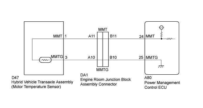
WIRING DIAGRAM
INSPECTION PROCEDURE
PROCEDURE
-
CHECK CONNECTOR CONNECTION CONDITION (POWER MANAGEMENT CONTROL ECU CONNECTOR)
-
Check the connections of the power management control ECU connectors.
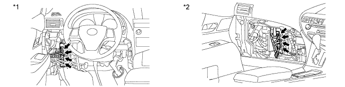
Text in Illustration *1 for LHD *2 for RHD OK The connectors are connected securely and there are no contact problems.
NG 
CONNECT SECURELY
OK 
-
-
CHECK CONNECTOR CONNECTION CONDITION (ENGINE ROOM JUNCTION BLOCK ASSEMBLY)
-
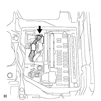
Check the connections of the engine room junction block assembly connectors.
OK The connectors are connected securely and there are no contact problems.
NG
CONNECT SECURELY
OK
-
-
READ VALUE USING INTELLIGENT TESTER (MOTOR TEMP NO1)
-
Connect the intelligent tester to the DLC3.
-
Turn the power switch on (IG).
-
Enter the following menus: Powertrain / Hybrid Control / Data List / Motor Temp No1.
-
Read the Data List.
Result Result Proceed to -40°C (-40°F) A 215°C (419°F) B Same as actual temperature C -
Turn the power switch off.
B 
READ VALUE USING INTELLIGENT TESTER (CHECK FOR SHORT) Click here
C
CHECK FOR INTERMITTENT PROBLEMS Click here
A
-
-
READ VALUE USING INTELLIGENT TESTER (CHECK FOR OPEN)
-
Disconnect connector DA1 from the engine room junction block assembly.
-
Connect terminals DA1-B11 (MMT) and DA1-B10 (MMTG) of the engine room junction block assembly.
-
Connect the intelligent tester to the DLC3.
-
Turn the power switch on (IG).
-
Enter the following menus: Powertrain / Hybrid Control / Data List / Motor Temp No1.
-
Read the Data List.
Result Tester Display Condition Specified Condition Motor Temp No1 Terminals MMT and MMTG connected.
Power switch on (IG)
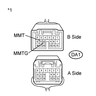
215°C (419°F) Text in Illustration *1 Front view of wire harness connector
(to Engine Room Junction Block Assembly)
-
Turn the power switch off.
-
Connect the engine room junction block assembly connector.
NG
CHECK HARNESS AND CONNECTOR (POWER MANAGEMENT CONTROL ECU - ENGINE ROOM JUNCTION BLOCK) Click here
OK
-
-
CHECK HARNESS AND CONNECTOR (MOTOR TEMPERATURE SENSOR - ENGINE ROOM JUNCTION BLOCK)
-
Disconnect connector DA1 from the engine room junction block assembly.
-
Remove the inverter with converter assembly Click here.
-
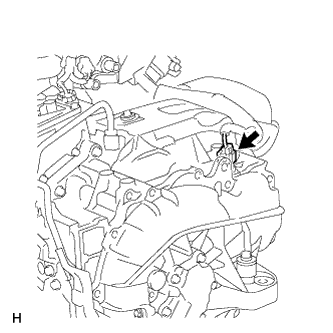
Disconnect the motor temperature sensor connector.
-
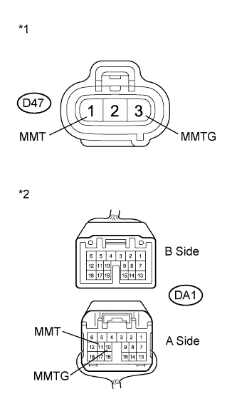
Text in Illustration *1 Front view of wire harness connector
(to Motor Temperature Sensor)
*2 Rear view of wire harness connector
(to Engine Room Junction Block Assembly)
Measure the resistance according to the value(s) in the table below.
Standard Resistance (Check for Open) Tester Connection Switch Condition Specified Condition D47-1 (MMT) - DA1-A11 (MMT) Power switch off Below 1 Ω D47-3 (MMTG) - DA1-A10 (MMTG) Power switch off Below 1 Ω Standard Resistance (Check for Short) Tester Connection Switch Condition Specified Condition D47-1 (MMT) or DA1-A11 (MMT) - Body ground and other terminals Power switch off 10 kΩ or higher D47-3 (MMTG) or DA1-A10 (MMTG) - Body ground and other terminals Power switch off 10 kΩ or higher -
Connect the motor temperature sensor connector.
-
Install the inverter with converter assembly.
-
Connect the engine room junction block assembly connector.
NG
REPAIR OR REPLACE HARNESS OR CONNECTOR
OK 
REPLACE HYBRID VEHICLE TRANSAXLE ASSEMBLY Click here
-
-
CHECK HARNESS AND CONNECTOR (POWER MANAGEMENT CONTROL ECU - ENGINE ROOM JUNCTION BLOCK)
-
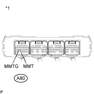
Text in Illustration *1 Component with harness connected
(Power Management Control ECU)
Connect terminals 24 (MMT) and 25 (MMTG) of the connector A80 of the power management control ECU.
-
Connect the intelligent tester to the DLC3.
-
Turn the power switch on (IG).
-
Enter the following menus: Powertrain / Hybrid Control / Data List / Motor Temp No1.
-
Read the Data List.
Result Tester Display Condition Specified Condition Motor Temp No1 Terminals MMT and MMTG connected.
Power switch on (IG)
215°C (419°F) Result Result Proceed to OK A NG (for LHD) B NG (for RHD) C -
Turn the power switch off.
B
REPLACE POWER MANAGEMENT CONTROL ECU (for LHD) Click here
C
REPLACE POWER MANAGEMENT CONTROL ECU (for RHD) Click here
A
REPAIR OR REPLACE HARNESS OR CONNECTOR
-
-
READ VALUE USING INTELLIGENT TESTER (CHECK FOR SHORT)
-
Disconnect connector from the engine room junction block assembly.
-
Connect the intelligent tester to the DLC3.
-
Turn the power switch on (IG).
-
Enter the following menus: Powertrain / Hybrid Control / Data List / Motor Temp No1.
-
Read the Data List.
Result Tester Display Condition Specified Condition Motor Temp No1 Power switch on (IG) -40°C (-40°F) -
Turn the power switch off.
NG
CHECK HARNESS AND CONNECTOR (POWER MANAGEMENT CONTROL ECU - ENGINE ROOM JUNCTION BLOCK) Click here
OK
-
-
CHECK HARNESS AND CONNECTOR (ENGINE ROOM JUNCTION BLOCK - MOTOR TEMPERATURE SENSOR)
-
Disconnect connector DA1 from the engine room junction block assembly.
-
Remove the inverter with converter assembly Click here.
-
Disconnect the motor temperature sensor connector.
-
Text in Illustration *1 Front view of wire harness connector
(to Motor Temperature Sensor)
*2 Rear view of wire harness connector
(to Engine Room Junction Block Assembly)
Measure the resistance according to the value(s) in the table below.
Standard Resistance (Check for Open) Tester Connection Switch Condition Specified Condition D47-1 (MMT) - DA1-A11 (MMT) Power switch off Below 1 Ω D47-3 (MMTG) - DA1-A10 (MMTG) Power switch off Below 1 Ω Standard Resistance (Check for Short) Tester Connection Switch Condition Specified Condition D47-1 (MMT) or DA1-A11 (MMT) - Body ground and other terminals Power switch off 10 kΩ or higher D47-3 (MMTG) or DA1-A10 (MMTG) - Body ground and other terminals Power switch off 10 kΩ or higher -
Connect the motor temperature sensor connector.
-
Install the inverter with converter assembly.
-
Connect the engine room junction block assembly connector.
NG
REPAIR OR REPLACE HARNESS OR CONNECTOR
OK
REPLACE HYBRID VEHICLE TRANSAXLE ASSEMBLY Click here
-
-
CHECK HARNESS AND CONNECTOR (POWER MANAGEMENT CONTROL ECU - ENGINE ROOM JUNCTION BLOCK)
-
Disconnect connector DA1 from the engine room junction block assembly.
-
Disconnect connector A80 from the power management control ECU.
-
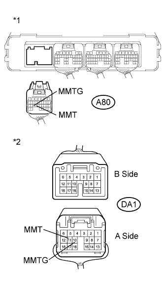
Text in Illustration *1 Front view of wire harness connector
(to Power Management Control ECU)
*2 Rear view of wire harness connector
(to Engine Room Junction Block Assembly)
Measure the resistance according to the value(s) in the table below.
Standard Resistance (Check for Open) Tester Connection Switch Condition Specified Condition A80-24 (MMT) - DA1-A11 (MMT) Power switch off Below 1 Ω A80-25 (MMTG) - DA1-A10 (MMTG) Power switch off Below 1 Ω Standard Resistance (Check for Short) Tester Connection Switch Condition Specified Condition A80-24 (MMT) or DA1-A11 (MMT) - Body ground and other terminals Power switch off 10 kΩ or higher A80-25 (MMTG) or DA1-A10 (MMTG) - Body ground and other terminals Power switch off 10 kΩ or higher Result Result Proceed to OK (for LHD) A OK (for RHD) B NG C -
Connect the power management control ECU connector.
-
Connect the engine room junction block assembly connector.
B
REPLACE POWER MANAGEMENT CONTROL ECU (for RHD) Click here
C
REPAIR OR REPLACE HARNESS OR CONNECTOR
A
REPLACE POWER MANAGEMENT CONTROL ECU (for LHD) Click here
-