HYBRID CONTROL SYSTEM DTC CHECK / CLEAR

-
CHECK DTC (POWER MANAGEMENT CONTROL ECU (HV CPU))
-
Connect the intelligent tester to the DLC3.
-
Turn the turn the power switch on (IG).
-
Turn the intelligent tester ON.
-
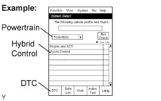
On the System Select screen, enter the following menus: Powertrain / Hybrid Control / DTC.
-
Read DTCs of the hybrid control system.
-
-
CHECK FREEZE FRAME DATA AND INFORMATION
-
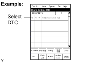
If a DTC is present, select that DTC in order to display its freeze frame data.
-
Read freeze frame data recorded when the DTC was set.
Note
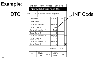
Information code (INF code) is displayed in one of the columns, detail code 1 to 5, on the freeze frame data screen. Check the details by following the procedures in the following steps.
Tech Tips
In the case shown in the illustration, refer to troubleshooting for DTC P3138 and INF code 349.
-
Read the information.
-
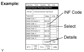
Select the Detail Information item beneath the Detail Code which has INF code.
Tech Tips
Detail Code 2 has the INF code 349 in the illustration. In this case, Detail Information 2 should be selected.
-
Press the "Details" key.
-
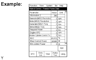
Information is displayed as shown in the illustration.
-
-
-
CHECK DTC (BUS CHECK)
-
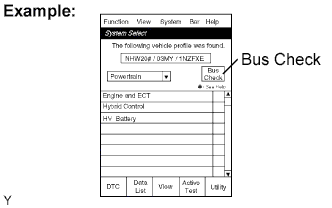
On the System Select screen, select Bus Check.
-
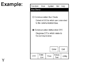
On the Bus Check screen, select Communication Malfunction DTC, in order to read the DTCs for a communication error.
Tech Tips
If DTCs for the CAN communication system are present in addition to other DTCs, first troubleshoot and repair malfunctions in the CAN communication system Click here.
-
-
CHECK FOR DTCS (SYSTEMS OTHER THAN POWER MANAGEMENT CONTROL ECU (HV CPU))
Tech Tips
The power management control ECU (HV CPU) maintains communication with other computers, including the ECM, skid control ECU, and power steering ECU. Therefore, if the power management control ECU (HV CPU) outputs a warning, it is necessary to check and record the DTCs of all systems.
-
If DTCs are present, check the relevant systems.
-
-
CLEAR DTCS
Note
Clearing the DTCs will also clear the freeze frame data, information Click here and operation history data Click here.
-
Connect the intelligent tester to the DLC3.
-
Turn the power switch on (IG) and turn the intelligent tester on.
-
Check that the shift lever is in P.
-
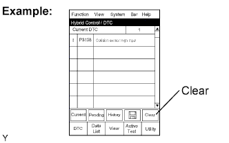
Display the Hybrid Control / DTC screen and press the Clear key at the bottom right area of the screen.
-
-
REPLACE INVERTER WITH CONVERTER ASSEMBLY PARTS
Note
This procedure is designed to be used as a reference for the inspection procedure of each DTC. Do not perform repairs using only this procedure.
-
Check the DTCs that were output when the vehicle was brought to the workshop. Refer to DTC Malfunctioning Area Table and replace parts as necessary.
Tech Tips
-
Using only the DTCs listed in the DTC Malfunctioning Area Table, perform the following judgment.
-
If multiple DTCs with different malfunctioning areas were output when the vehicle was brought to the workshop, replace all of the respective malfunctioning parts. If any of the output DTCs list the inverter with converter assembly as the malfunctioning area, it is only necessary to replace the inverter with converter assembly.
-
If any malfunctions of inverter with converter assembly related parts are found, or if signs of coolant (LLC) leaks, water intrusion, excessive deposits or damage are found in the inverter with converter assembly, replace the inverter with converter assembly.
-
-
-
DTC MALFUNCTIONING AREA TABLE
-
Using DTC Malfunctioning Area Table, confirm the malfunctioning area indicated by the DTC.
DTC Malfunctioning Area Table DTC Motor Generator Control Computer Inverter with Converter Assembly P0069-273 - ○ P0340-886 - ○ P0343-747 ○ - P0A01-726 - ○ P0A02-719 - ○ P0A03-720 - ○ P0A04-725 - ○ P0A08-264 - ○ P0A09-265 - ○ P0A09-591 - ○ P0A0D-350 - ○ P0A0D-351 - ○ P0A10-263 - ○ P0A10-592 - ○ P0A1A-151 ○ - P0A1A-155 ○ - P0A1A-156 ○ - P0A1A-166 ○ - P0A1A-200 ○ - P0A1A-658 ○ - P0A1A-659 ○ - P0A1A-791 ○ - P0A1A-792 ○ - P0A1A-793 ○ - P0A1B-163 ○ - P0A1B-164 ○ - P0A1B-168 ○ - P0A1B-192 ○ - P0A1B-193 ○ - P0A1B-198 ○ - P0A1B-511 ○ - P0A1B-512 ○ - P0A1B-661 ○ - P0A1B-786 ○ - P0A1B-794 ○ - P0A1B-795 ○ - P0A1B-796 ○ - P0A1C-706 - ○ P0A1C-708 - ○ P0A1C-709 ○ - P0A1C-710 - ○ P0A1C-713 - ○ P0A1C-715 - ○ P0A1C-797 - ○ P0A1C-798 - ○ P0A1C-799 - ○ P0A3F-243 - ○ P0A40-500 - ○ P0A41-245 - ○ P0A45-669 - ○ P0A46-671 ○ - P0A47-670 ○ - P0A4B-253 - ○ P0A4C-513 - ○ P0A4D-255 ○ - P0A51-174 - ○ P0A55-687 - ○ P0A60-288 - ○ P0A60-290 - ○ P0A60-294 - ○ P0A60-501 - ○ P0A63-296 - ○ P0A63-298 - ○ P0A63-302 - ○ P0A63-502 - ○ P0A69-677 - ○ P0A69-683 - ○ P0A69-684 - ○ P0A69-688 - ○ P0A6C-678 - ○ P0A6C-685 - ○ P0A6C-686 - ○ P0A6C-689 - ○ P0A72-326 - ○ P0A72-328 - ○ P0A72-333 - ○ P0A72-515 - ○ P0A75-334 - ○ P0A75-336 - ○ P0A75-341 - ○ P0A75-516 - ○ P0A78-113 - ○ P0A78-118 - ○ P0A78-119 - ○ P0A78-120 - ○ P0A78-121 - ○ P0A78-128 - ○ P0A78-202 - ○ P0A78-266 - ○ P0A78-267 - ○ P0A78-279 - ○ P0A78-282 - ○ P0A78-284 - ○ P0A78-286 - ○ P0A78-287 - ○ P0A78-306 - ○ P0A78-503 - ○ P0A78-504 - ○ P0A78-505 - ○ P0A78-506 - ○ P0A78-510 - ○ P0A78-565 - ○ P0A78-586 - ○ P0A78-806 - ○ P0A78-807 - ○ P0A78-808 - ○ P0A79-136 - ○ P0A79-692 - ○ P0A79-693 - ○ P0A79-694 - ○ P0A79-695 - ○ P0A79-696 - ○ P0A79-703 - ○ P0A79-704 - ○ P0A79-712 - ○ P0A79-716 - ○ P0A79-812 - ○ P0A79-813 - ○ P0A79-814 - ○ P0A7A-122 - ○ P0A7A-130 - ○ P0A7A-203 - ○ P0A7A-322 - ○ P0A7A-324 - ○ P0A7A-325 - ○ P0A7A-344 - ○ P0A7A-517 - ○ P0A7A-518 - ○ P0A7A-522 - ○ P0A7A-809 - ○ P0A7A-810 - ○ P0A7A-811 - ○ P0A90-509 - ○ P0A91-702 - ○ P0A92-521 - ○ P0A93-346 - ○ P0A94-124 - ○ P0A94-125 - ○ P0A94-126 - ○ P0A94-127 - ○ P0A94-169 - ○ P0A94-170 - ○ P0A94-171 - ○ P0A94-172 - ○ P0A94-442 - ○ P0A94-547 - ○ P0A94-548 - ○ P0A94-549 - ○ P0A94-550 - ○ P0A94-553 - ○ P0A94-554 - ○ P0A94-555 - ○ P0A94-556 - ○ P0A94-557 - ○ P0A94-564 - ○ P0A94-585 - ○ P0A94-587 - ○ P0A94-589 - ○ P0A94-590 - ○ P0AA1-231 - ○ P0AA4-232 - ○ P0AA6-526 - ○ P0AA6-613 - ○ P0AA6-614 - ○ P0AA6-655 - ○ P0AE2-773 - ○ P0AEE-277 - ○ P0AEF-275 - ○ P0AF0-274 - ○ P0AF1-276 - ○ P0AF3-676 - ○ P0AF4-673 - ○ P0AF5-674 - ○ P0AF6-675 - ○ P0BCD-315 - ○ P0BCE-313 - ○ P0BCF-312 - ○ P0BD0-314 - ○ P0C39-626 - ○ P0C3A-621 - ○ P0C3B-622 - ○ P0C3C-625 - ○ P0C3E-628 - ○ P0C3F-623 - ○ P0C40-624 - ○ P0C41-627 - ○ P0C76-523 - ○ P2228-268 ○ - P2229-269 ○ - P3004-131 - ○ P3004-132 - ○ P3004-800 - ○ P3004-801 - ○ P310A-711 - ○ P310B-662 - ○ P3232-749 - ○ P3233-750 - ○ P324E-788 ○ - U0110-159 - ○ U0110-160 ○ - U0110-656 - ○ U0110-657 - ○
-
-
DTC OUTPUT CONFIRMATION OPERATION
Tech Tips
If inverter with converter assembly related DTCs are output, perform repairs then check the operation and check for DTCs as follows.
-
Connect the intelligent tester to the DLC3.
-
Turn the power switch on (IG) and clear the DTCs by following the prompts on the intelligent tester screen.
-
Turn the power switch on (IG) and wait for 5 seconds or more.
-
Turn the power switch on (READY) with the shift lever in P and wait for 5 seconds or more.
-
Move the shift lever to N and wait for 5 seconds or more.
-
Warm up the engine with the shift lever in P and the A/C off. (The engine may start automatically when cold. Warm up the engine until it stops.)
Tech Tips
The engine will stop on its own when it is warmed up.
-
Depress the accelerator pedal with the shift lever in P to start the engine.(*1)
Tech Tips
When the accelerator pedal is fully depressed with the shift lever in P, the engine speed will increase to approximately 1800 rpm. Release the accelerator pedal as soon as the engine starts.
-
Wait until the engine stops without depressing the accelerator pedal. (*2)
-
Repeat steps (*1) and (*2) 10 times.
-
Move the shift lever to D. Creep the vehicle forward 5 m with the engine stopped and without depressing the accelerator pedal.
Note
Confirm the safety of the surrounding area before moving the vehicle.
-
Move the shift lever to R. Creep the vehicle backward 5 m with the engine stopped and without depressing the accelerator pedal.
Note
Confirm the safety of the surrounding area before moving the vehicle.
-
Check for DTCs by following the prompts on the intelligent tester screen.
-
If no DTCs are output, drive the vehicle on city roads for approximately 10 minutes (until the vehicle is driven at 40 km/h or more for a total of 5 minutes or more).
-