HYBRID CONTROL SYSTEM SYSTEM DESCRIPTION

-
BASIC OPERATION
-
This system generates a motive force in combination with the engine, MG1, MG2, and MGR in accordance with the driving conditions. Representative examples of the various combinations are described below.
-
Front Wheel Operation:
-
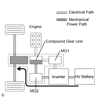
Supply of electrical power from the HV battery to MG2 provides force to drive the front wheels.
-
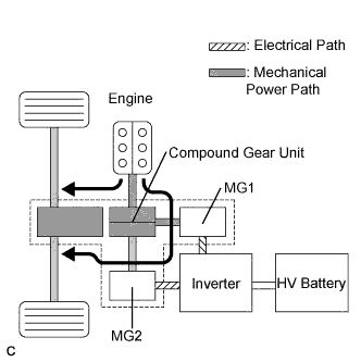
While the front wheels are being driven by the engine via the planetary gears, MG1 is driven by the engine via the planetary gears, in order to supply the generated electricity to MG2.
-
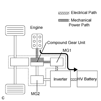
MG1 is rotated by the engine via the planetary gears, in order to charge the HV battery.
-
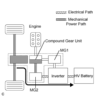
When the vehicle is decelerating, kinetic energy from the front wheels is recovered and converted into electrical energy and used to recharge the HV battery by means of MG2.
-
-
Rear Wheel Operation:
-
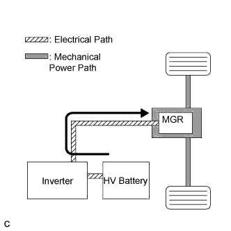
To ensure the proper driving force of the vehicle during start-off or acceleration, the electrical power of the HV battery is supplied to MGR in order to drive the rear wheels.
-
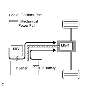
During the full throttle acceleration of the vehicle, both the electrical power of the HV battery and the electrical power generated by MG1 are supplied to MGR in order to drive the rear wheels.
-
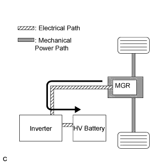
When the vehicle is decelerating, kinetic energy from the rear wheels is recovered and converted into electrical energy and used to recharge the HV battery by means of MGR.
-
-
-
SYSTEM DIAGRAM
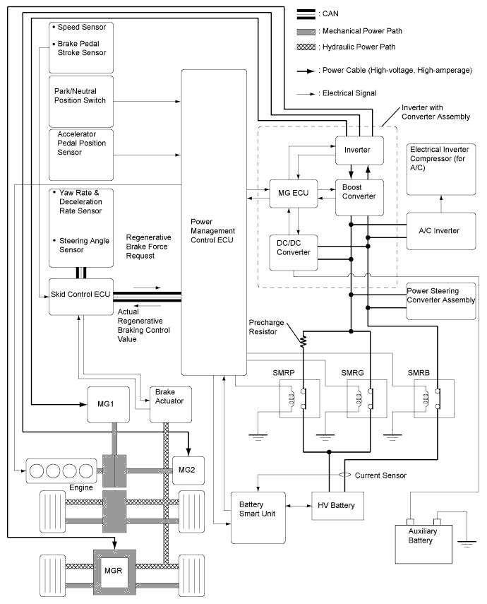
-
FUNCTION OF MAIN COMPONENTS
Component Function Hybrid Vehicle Transaxle Assembly Motor Generator 1 (MG1)
-
MG1, which is driven by the engine, generates high-voltage electricity in order to operate MG2 and MGR and/or charge the HV battery. Also, it functions as a starter to start the engine.
-
MG1 is operated so that the gear ratio of the power split planetary gear unit will optimally suit the driving conditions of the vehicle.
Motor Generator 2 (MG2)
-
Driven by electrical power from MG1 and/or the HV battery, it generates motive force for the front wheels.
-
During braking, or when the accelerator pedal is not depressed, it generates electricity to recharge the HV battery (Regenerative braking).
Compound Gear Unit Power Split Planetary Gear Unit:
-
Distributes the engine drive force as appropriate to directly drive the vehicle as well as MG1.
Motor Speed Reduction Planetary Gear Unit:
-
Located between MG2 and the power split planetary gear, the motor speed reduction planetary gear reduces the rotational speed of MG2 in order to increase torque.
Resolver
-
MG1 and MG2 are each equipped with a resolver.
-
Sends the rotational speed and direction of the motor to the Motor Generator ECU (MG ECU).
Temperature Sensor
-
MG1 and MG2 are each equipped with a temperature sensor.
-
Measures the temperature of MG1 and MG2.
Rear Traction Motor with Transaxle Assembly Motor Generator Rear (MGR)
-
Driven by electrical power from MG1 and/or the HV battery, it generates motive force for the rear wheels.
-
During braking, or when the accelerator pedal is not depressed, it generates electricity to recharge the HV battery (Regenerative braking).
Resolver
-
MGR is equipped with a resolver.
-
Sends the rotational speed and direction of the motor to the Motor Generator ECU (MG ECU).
Temperature Sensor
-
MGR is equipped with a temperature sensor.
-
Measures the temperature of MGR.
Inverter with Converter Assembly Inverter A device that converts high-voltage DC (HV battery) into AC (MG1, MG2 and MGR) and vice versa (converts AC into DC). Boost Converter Boosts the voltage of the HV battery from DC 288 V to a maximum of DC 650 V and vice versa (drops DC 650 V to DC 288 V). DC/DC Converter Drops the HV battery voltage of DC 288 V to approximately DC 14 V in order to supply electricity to body electrical components, as well as to recharge the auxiliary battery. Motor Generator ECU (MG ECU) Controls the inverter and boost converter in accordance with signals received from the power management control ECU (HV CPU), thus operating MG1, MG2, or MGR as either a generator or motor. Temperature Sensors (6)
-
Inverter temperature sensors are provided for the boost converter (2), power module for MG1, MG2 and MGR and coolant.
-
Measures the temperature of boost converter, power module for MG1, MG2 and MGR and coolant.
Current Sensors (6)
-
MG1, MG2 and MGR are each provided with 2 current sensors.
-
Measures the current of the MG1, MG2 and MGR
Power Management Control ECU (HV CPU)
-
Performs comprehensive control of the hybrid control system. This includes the electric continuously variable transmission and HV battery.
-
Information from various sensors as well as from ECUs (battery smart unit, Motor Generator ECU (MG ECU), skid control ECU, and power steering ECU) is received, and based on this the required torque and output power is calculated. The power management control ECU (HV CPU) sends the calculated result to the Motor Generator ECU (MG ECU) and skid control ECU.
-
Monitors the State Of Charge (SOC) of the HV battery.
-
Controls the battery cooling blower assemblies.
-
Controls the DC/DC converter.
ECM The ECM transmits the operating condition of the engine to the power management control ECU (HV CPU). HV Battery Assembly
-
Supplies electrical power to MG1, MG2, and MGR in accordance with the driving conditions of the vehicle.
-
Is charged by MG1, MG2, and MGR in accordance with the SOC and the driving conditions of the vehicle.
-
Has a nominal (approximate) voltage of DC 288 V (actual voltage will vary depending on various conditions such as temperature, charge or discharge).
Hybrid Junction Block Assembly System Main Relays (SMRs) Connect and disconnect the high-voltage power circuit between battery and inverter with converter assembly. The power management control ECU (HV CPU) controls the SMRs by turning them on or off as appropriate HV Battery Current Sensor Measures the current of the HV battery. Battery Smart Unit
-
Monitors HV battery conditions such as voltage, temperature and current, and transmits this information to the power management control ECU (HV CPU).
-
Monitors the HV system for breakdown of the electrical insulation.
Skid Control ECU
-
During braking, it calculates the regenerative braking force that is required and transmits it to the power management control ECU (HV CPU).
-
Calculates the motive force that is required during the operation of TRC or VSC and transmits it to the power management control ECU (HV CPU).
-
Transmits a front and rear wheel torque distribution request to the power management control ECU (HV CPU) for the purpose of E-four system control.
Accelerator Pedal Position Sensor Converts the accelerator pedal position into an electrical signal and outputs it to the power management control ECU (HV CPU). Shift Lever Position Sensor Converts the shift lever position into electrical signals and outputs them to the power management control ECU (HV CPU). Interlock Switch (3)
- Inverter Terminal Cover
- Service Plug Grip
- Power Cable
Verifies that the inverter terminal cover, service plug grip and power cable are installed. Service Plug Grip Can be removed to open the internal high-voltage circuit of the HV battery for vehicle inspection or maintenance. Inverter Radiator Provided for inverter cooling. Inverter Water Pump Assembly Controlled to 3 stages by the power management control ECU (HV CPU) according to inverter coolant temperature in order to cool the inverter. Power Cable Connect the HV battery with inverter with converter assembly, the HV battery with power steering converter assembly , the inverter with converter assembly with MG1, MG2 and MGR, and the inverter with converter with the compressor with motor assembly. Auxiliary Battery When the power switch is on, the auxiliary battery supplies power to the electrical equipment and ECUs. Auxiliary Battery Temperature Sensor
(Thermistor Assembly)
Measures the temperature of the auxiliary battery for auxiliary battery protection. Oil Pump with Motor Assembly The oil pump with motor assembly is controlled by the power management control ECU (HV CPU) to cool ATF according to the Motor Generator (MG) temperature. -