HYBRID CONTROL SYSTEM, Diagnostic DTC:P0340-886

| DTC Code | DTC Name |
|---|---|
| P0340-886 | Camshaft Position Sensor "A" Circuit |
DESCRIPTION
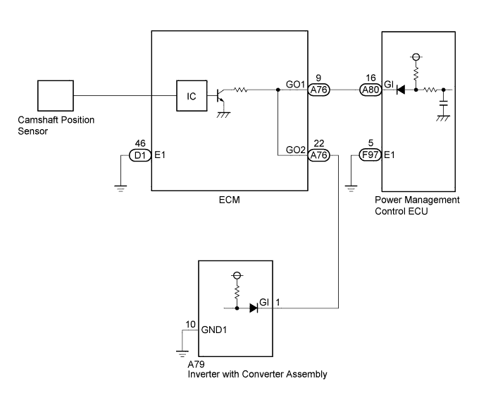
The power management control ECU (HV CPU) compares the engine speed sent from the ECM via CAN communication and the engine speed that is indicated by pulses sent from the ECM. If the pulse input is not normal, the power management control ECU (HV CPU) sets this DTC.
| DTC No. | INF Code | DTC Detection Condition | Trouble Area |
|---|---|---|---|
| P0340 | 886 | Malfunction in the engine speed sensor (GI signal) circuit |
|
WIRING DIAGRAM
INSPECTION PROCEDURE
CAUTION:
-
Before inspecting the high-voltage system or disconnecting the low voltage connector of the inverter with converter assembly, take safety precautions such as wearing insulated gloves and removing the service plug grip to prevent electrical shocks. After removing the service plug grip, put it in your pocket to prevent other technicians from accidentally reconnecting it while you are working on the high-voltage system.
-
After disconnecting the service plug grip, wait for at least 10 minutes before touching any of the high-voltage connectors or terminals. After waiting for 10 minutes, check the voltage at the terminals in the inspection point in the inverter with converter assembly. The voltage should be 0 V before beginning work.
Tech Tips
Waiting for at least 10 minutes is required to discharge the high-voltage capacitor inside the inverter with converter assembly.
PROCEDURE
-
CHECK DTC OUTPUT (HV)
-
Connect the intelligent tester to the DLC3.
-
Turn the power switch on (IG).
-
Enter the following menus: Powertrain / Hybrid Control / Trouble Codes.
-
Check if DTCs are output.
Result Result Proceed to DTC P0340-886 only is output. A DTC P0343-747 is also output. B
B 
CHECK HARNESS AND CONNECTOR (ECM - POWER MANAGEMENT CONTROL ECU, INVERTER WITH CONVERTER) Click here
A 
-
-
CHECK CONNECTOR CONNECTION CONDITION (ECM CONNECTOR)
-
Check the connections of the ECM connectors.
OK The connectors are connected securely and there are no contact problems.
NG 
CONNECT SECURELY
OK
-
-
CHECK CONNECTOR CONNECTION CONDITION (POWER MANAGEMENT CONTROL ECU CONNECTOR)
-
Check the connections of the power management control ECU connectors.
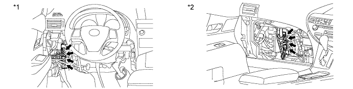
Text in Illustration *1 for LHD *2 for RHD OK The connectors are connected securely and there are no contact problems.
NG
CONNECT SECURELY
OK
-
-
CHECK HARNESS AND CONNECTOR (POWER MANAGEMENT CONTROL ECU)
-
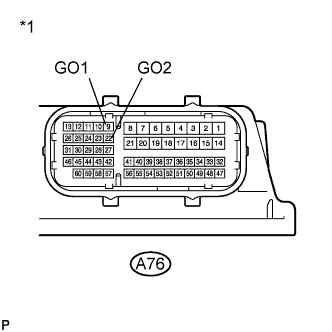
Disconnect the A76 connector from the ECM.
-
Turn the power switch on (IG).
-
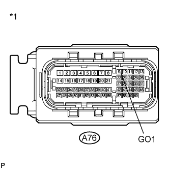
Text in Illustration *1 Front view of wire harness connector
(to ECM)
Measure the voltage according to the value(s) in the table below.
Standard Voltage Tester Connection Switch Condition Specified Condition A76-9 (GO1) - Body ground Power switch on (IG) 11 to 14 V Note
Turning the power switch on (IG) with the ECM connector disconnected causes other DTCs to be stored. Clear the DTCs after performing this inspection.
-
Turn the power switch off.
-
Connect the ECM connector.
NG
CHECK HARNESS AND CONNECTOR (ECM - POWER MANAGEMENT CONTROL ECU) Click here
OK
-
-
CHECK ECM
-
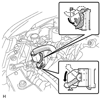
Remove the ECM.
-
Text in Illustration *1 Component without harness connected
(ECM)
Measure the resistance according to the value(s) in the table below.
Standard Resistance Tester Connection Switch Condition Specified Condition A76-9 (GO1) - A76-22 (GO2) Always Below 1 Ω Result Result Proceed to OK (for LHD) A OK (for RHD) B NG C -
Install the ECM.
B
REPLACE POWER MANAGEMENT CONTROL ECU (for RHD) Click here
C
REPLACE ECM Click here
A 
REPLACE POWER MANAGEMENT CONTROL ECU (for LHD) Click here
-
-
CHECK HARNESS AND CONNECTOR (ECM - POWER MANAGEMENT CONTROL ECU)
-
Disconnect the A76 connector from the ECM.
-
Disconnect the A80 connector from the power management control ECU.
-
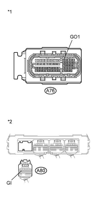
Text in Illustration *1 Front view of wire harness connector
(to ECM)
*2 Rear view of wire harness connector
(to Power Management Control ECU)
Measure the resistance according to the value(s) in the table below.
Standard Resistance Tester Connection Switch Condition Specified Condition A76-9 (GO1) - A80-16 (GI) Power switch off Below 1 Ω A76-9 (GO1) or A80-16 (GI) - Body ground and other terminals Power switch off 10 kΩ or higher Result Result Proceed to OK (for LHD) A OK (for RHD) B NG C -
Connect the ECM connector.
-
Connect the power management control ECU connector.
B
REPLACE POWER MANAGEMENT CONTROL ECU (for RHD) Click here
C
REPAIR OR REPLACE HARNESS OR CONNECTOR
A
REPLACE POWER MANAGEMENT CONTROL ECU (for LHD) Click here
-
-
CHECK HARNESS AND CONNECTOR (ECM - POWER MANAGEMENT CONTROL ECU, INVERTER WITH CONVERTER)
CAUTION:
Be sure to wear insulated gloves.
-
Check that the service plug grip is not installed.
Note
After removing the service plug grip, do not turn the power switch on (READY), unless instructed by the repair manual because this may cause a malfunction.
-
Disconnect theA76 connector from the ECM.
-
Disconnect the A80 connector from the power management control ECU.
-
Disconnect the A79 connector from the inverter with converter assembly.
-
Turn the power switch on (IG).
-
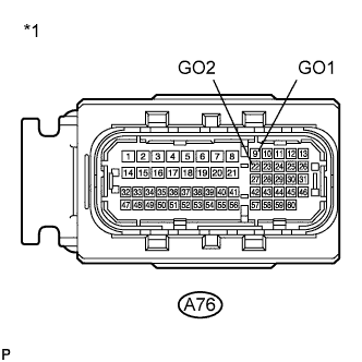
Text in Illustration *1 Front view of wire harness connector
(to ECM)
Measure the voltage according to the value(s) in the table below.
Standard Voltage Tester Connection Switch Condition Specified Condition A76-9 (GO1) - Body ground Power switch on (IG) Below 1 V A76-22 (GO2) - Body ground Power switch on (IG) Below 1 V Note
Turning the power switch on (IG) with the inverter with converter assembly connector, power management control ECU and ECM connectors disconnected causes other DTCs to be stored. Clear the DTCs after performing this inspection.
-
Turn the power switch off.
-
Measure the resistance according to the value(s) in the table below.
Standard Resistance Tester Connection Switch Condition Specified Condition A76-9 (GO1) - Body ground Power switch off 10 kΩ or higher A76-22 (GO2) - Body ground Power switch off 10 kΩ or higher -
Connect the ECM connector.
-
Connect the power management control ECU connector.
-
Connect the inverter with converter assembly connector.
NG
REPAIR OR REPLACE HARNESS OR CONNECTOR
OK
-
-
CHECK POWER MANAGEMENT CONTROL ECU
-
Disconnect all the connectors from the power management control ECU.
-
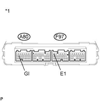
Text in Illustration *1 Component without harness connected
(Power Management Control ECU)
Measure the resistance according to the value(s) in the table below.
Standard Resistance Tester Connection Switch Condition Specified Condition A80-16 (GI) - F97-6 (E1) Always 10 kΩ or higher Result Result Proceed to OK A NG (for LHD) B NG (for RHD) C -
Connect the power management control ECU connectors.
B
REPLACE POWER MANAGEMENT CONTROL ECU (for LHD) Click here
C
REPLACE POWER MANAGEMENT CONTROL ECU (for RHD) Click here
A
-
-
CHECK INVERTER WITH CONVERTER ASSEMBLY
CAUTION:
Be sure to wear insulated gloves.
-
Check that the service plug grip is not installed.
Note
After removing the service plug grip, do not turn the power switch on (READY), unless instructed by the repair manual because this may cause a malfunction.
-
Disconnect the A79 connector from the inverter with converter assembly.
-
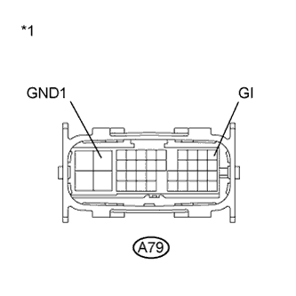
Text in Illustration *1 Component without harness connected
(Inverter with Converter Assembly)
Measure the resistance according to the value(s) in the table below.
Standard Resistance Tester Connection Switch Condition Specified Condition A79-1 (GI) - A79-10 (GND1) Power switch off 10 kΩ or higher -
Connect the inverter with converter assembly connector.
NG
REPLACE INVERTER WITH CONVERTER ASSEMBLY Click here
OK
REPLACE ECM Click here
-