SFI SYSTEM (w/o EGR System), Diagnostic DTC:P2118

| DTC Code | DTC Name |
|---|---|
| P2118 | Throttle Actuator Control Motor Current Range / Performance |
DESCRIPTION
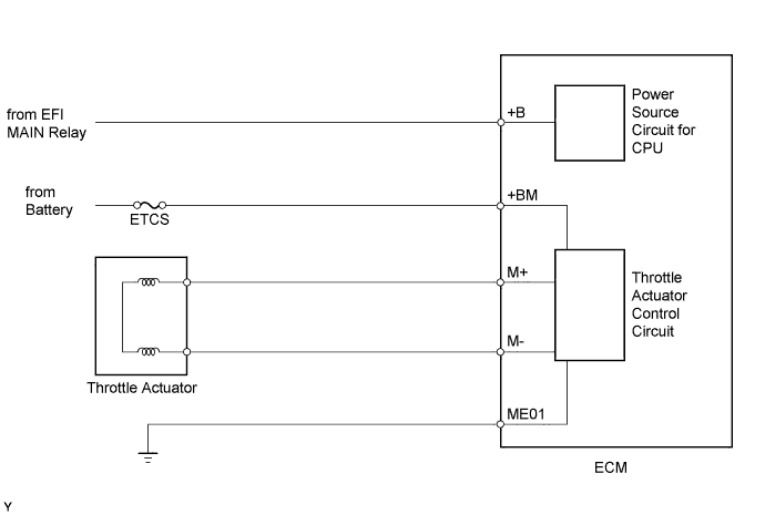
The electronic throttle control system has a dedicated power supply circuit. The voltage (+BM) is monitored and when it is low (below 4 V), the ECM determines that there is a malfunction in the electronic throttle control system and cuts off the current to the throttle actuator.
When the voltage becomes unstable, the electronic throttle control system itself becomes unstable. For this reason, when the voltage is low, the current to the throttle actuator is cut. If repairs are made and the system returns to normal, turn the power switch off. The ECM then allows the current to flow to the throttle actuator so that it can be restarted.
Tech Tips
This electronic throttle control system does not use a throttle cable.
| DTC No. | DTC Detection Condition | Trouble Area |
|---|---|---|
| P2118 | Open in electronic throttle control system power source (+BM) circuit (1 trip detection logic) |
|
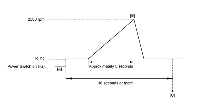
CONFIRMATION DRIVING PATTERN
-
Connect the intelligent tester to the DLC3.
-
Turn the power switch on (IG) and turn the tester on.
-
Clear the DTCs (even if no DTCs are stored, perform the clear DTC operation).
-
Turn the power switch off and wait for 30 seconds.
-
Turn the power switch on (IG) and turn the tester on [A].
-
Put the engine in inspection mode (maintenance mode) Click here.
-
Start the engine.
-
Slowly depress the accelerator pedal, raise the engine speed to approximately 2500 rpm for approximately 5 seconds, and then idle the engine [B].
-
Enter the following menus: Powertrain / Engine and ECT / DTC [C].
-
Read the pending DTCs.
Tech Tips
-
If a pending DTC is output, the system is malfunctioning.
-
If a pending DTC is not output, perform the following procedure.
-
-
Enter the following menus: Powertrain / Engine and ECT / Utility / All Readiness.
-
Input the DTC: P2118.
-
Check the DTC judgment result.
Tester Display Description NORMAL
-
DTC judgment completed
-
System normal
ABNORMAL
-
DTC judgment completed
-
System abnormal
INCOMPLETE
-
DTC judgment not completed
-
Perform driving pattern after confirming DTC enabling conditions
N/A
-
Unable to perform DTC judgment
-
Number of DTCs which do not fulfill DTC preconditions has reached ECU memory limit
Tech Tips
-
If the judgment result shows NORMAL, the system is normal.
-
If the judgment result shows ABNORMAL, the system has a malfunction.
-
If the judgment result shows INCOMPLETE or N/A, perform steps [B] through [C] again.
-
FAIL-SAFE
When either of these DTCs, as well as other DTCs relating to electronic throttle control system malfunctions is stored, the ECM enters fail-safe mode. During fail-safe mode, the ECM cuts the current to the throttle actuator, and the throttle valve is returned to a 6° throttle angle by the return spring. The ECM stops the engine and the vehicle can be driven using solely the hybrid system. If the accelerator pedal is depressed firmly and gently, the vehicle can be driven slowly.
Fail-safe mode continues until a pass condition is detected, and the power switch is then turned off.
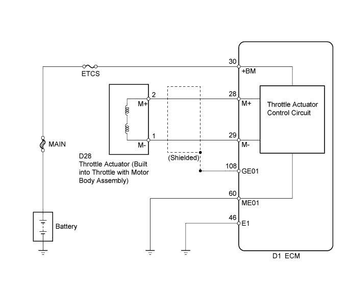
WIRING DIAGRAM
INSPECTION PROCEDURE
Note
Inspect the fuses for circuit related to this system before performing the following inspection procedure.
Tech Tips
Read freeze frame data using the intelligent tester. The ECM records vehicle and driving condition information as freeze frame data the moment a DTC is stored. When troubleshooting, freeze frame data can help determine if the vehicle was moving or stationary, if the engine was warmed up or not, if the air fuel ratio was lean or rich, and other data from the time the malfunction occurred.
PROCEDURE
-
READ VALUE USING INTELLIGENT TESTER (+BM VOLTAGE)
-
Connect the intelligent tester to the DLC3.
-
Turn the power switch on (IG).
-
Turn the tester on.
-
Enter the following menus: Powertrain / Engine and ECT / Data List / All Data / +BM voltage.
-
Read the value displayed on the tester.
Standard Voltage 11 to 14 V
NG 
CHECK HARNESS AND CONNECTOR (ECM - BATTERY, BODY GROUND) Click here
OK 
CHECK FOR INTERMITTENT PROBLEMS Click here
-
-
CHECK HARNESS AND CONNECTOR (ECM - BATTERY, BODY GROUND)
-
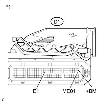
Text in Illustration *1 Front view of wire harness connector
(to ECM)
Disconnect the ECM connectors.
-
Measure the voltage according to the value(s) in the table below.
Standard Voltage Tester Connection Condition Specified Condition D1-30 (+BM) - Body ground Always 11 to 14 V -
Measure the resistance according to the value(s) in the table below.
Standard Resistance (Check for Open) Tester Connection Condition Specified Condition D1-60 (ME01) - Body ground Always Below 1 Ω D1-46 (E1) - Body ground Always Below 1 Ω -
Reconnect the ECM connector.
NG 
REPAIR OR REPLACE HARNESS OR CONNECTOR (ECM - BATTERY, BODY GROUND)
OK
REPLACE ECM Click here
-