SFI SYSTEM (w/o EGR System), Diagnostic DTC:P0016, P0018

| DTC Code | DTC Name |
|---|---|
| P0016 | Crankshaft Position - Camshaft Position Correlation (Bank 1 Sensor A) |
| P0018 | Crankshaft Position - Camshaft Position Correlation (Bank 2 Sensor A) |
DESCRIPTION
Refer to DTC P0010 Click here.
| DTC No. | DTC Detection Condition | Trouble Area |
|---|---|---|
| P0016 | Deviations in crankshaft and camshaft position sensor signals (2 trip detection logic) |
|
| P0018 | Deviations in crankshaft and camshaft position sensor signal (2 trip detection logic) |
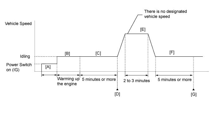
CONFIRMATION DRIVING PATTERN
-
Connect the intelligent tester to the DLC3.
-
Turn the power switch on (IG) and turn the tester on.
-
Clear the DTCs (even if no DTCs are stored, perform the clear DTC procedure) Click here.
-
Turn the power switch off.
-
Turn the power switch on (IG) and turn the tester on [A].
-
Put the engine in inspection mode Click here.
-
Start the engine and warm it up until the engine coolant temperature reaches 75°C (167°F) or more [B].
-
Idle the engine for 5 minutes or more [C].
-
Enter the following menus: Powertrain / Engine and ECT / DTC / Pending [D].
-
Read the pending DTC.
-
If a pending DTC is output, the system is malfunctioning.
Tech Tips
If a pending DTC is not output, perform the following procedure.
-
Enter the following menus: Powertrain / Engine and ECT / Utility / All Readiness.
-
Input the DTC: P0016 or P0018.
-
Check the DTC judgment result.
Tester Display Description NORMAL
-
DTC judgment completed
-
System normal
ABNORMAL
-
DTC judgment completed
-
System abnormal
INCOMPLETE
-
DTC judgment not completed
-
Perform driving pattern after confirming DTC enabling conditions
N/A
-
Unable to perform DTC judgment
-
Number of DTCs which do not fulfill DTC preconditions has reached ECU's memory limit
Tech Tips
-
If the judgment result shows ABNORMAL, the system has a malfunction.
-
If the judgment result shows INCOMPLETE or N/A, perform steps [E] through [G].
-
-
Drive the vehicle for 2 to 3 minutes [E].
CAUTION:
When performing the confirmation driving pattern, obey all speed limits and traffic laws.
-
Idle the engine for 5 minutes or more [F].
-
Enter the following menus: Powertrain / Engine and ECT / Utility / All Readiness.
-
Input the DTC: P0016 or P0018.
-
Check the DTC judgment result again [G].
WIRING DIAGRAM
Refer to DTC P0010 Click here.
INSPECTION PROCEDURE
Tech Tips
-
Read freeze frame data using the intelligent tester. The ECM records vehicle and driving condition information as freeze frame data the moment a DTC is stored. When troubleshooting, freeze frame data can help determine if the vehicle was moving or stationary, if the engine was warmed up or not, if the air fuel ratio was lean or rich, and other data from the time the malfunction occurred.
-
Bank 1 refers to the bank that includes the No. 1 cylinder*.
*: The No. 1 cylinder is the cylinder which is farthest from the transaxle.
-
Bank 2 refers to the bank that does not include the No. 1 cylinder.
PROCEDURE
-
CHECK ANY OTHER DTCS OUTPUT (IN ADDITION TO DTC P0016 OR P0018)
-
Connect the intelligent tester to the DLC3.
-
Turn the power switch on (IG).
-
Turn the tester on.
-
Enter the following menus: Powertrain / Engine and ECT / DTC.
-
Read the DTCs.
Result Result Proceed to DTC P0016 or P0018 is output A DTC P0016 or P0018 and other DTCs are output B Tech Tips
If any DTCs other than P0016 or P0018 are output, troubleshoot those DTCs first.
B 
GO TO DTC CHART Click here
A 
-
-
PERFORM ACTIVE TEST USING INTELLIGENT TESTER (CONTROL THE VVT LINEAR (BANK 1 OR 2))
-
Connect the intelligent tester to the DLC3.
-
Turn the power switch on (IG).
-
Turn the tester on.
-
Put the engine in inspection mode Click here.
-
Start the engine.
-
Warm up the engine.
-
Enter the following menus: Powertrain / Engine and ECT / Active Test / Control the VVT Linear (Bank 1) or Control the VVT Linear (Bank 2).
-
Check the engine speed while operating the camshaft timing oil control valve assembly using the tester.
OK Tester Operation Engine Condition 0% Normal engine speed 100% Engine idles roughly or stalls Tech Tips
Test not possible with shift lever in P position during charge control, move shift lever to N to perform test.
NG 
OK
-
-
CHECK WHETHER DTC OUTPUT RECURS (P0016 OR P0018)
-
Connect the intelligent tester to the DLC3.
-
Turn the power switch on (IG).
-
Turn the tester on.
-
Clear the DTCs Click here.
-
Turn the power switch off.
-
Turn the power switch on (IG) and turn the tester on.
-
Put the engine in inspection mode Click here.
-
Start the engine and warm it up.
-
Drive the vehicle in accordance with the driving pattern described in the Confirmation Driving Pattern.
-
Enter the following menus: Powertrain / Engine and ECT / DTC / Pending.
-
Read the DTCs.
Result Result Proceed to DTC is not output A DTC P0016 or P0018 is output B Tech Tips
DTC P0016 or P0018 is output when foreign objects in engine oil are caught in some parts of the system. These codes will remain stored even if the system returns to normal after a short time. These foreign objects may then be captured by the oil filter, thus eliminating the source of the problem.
B
A 
CHECK FOR INTERMITTENT PROBLEMS Click here
-
-
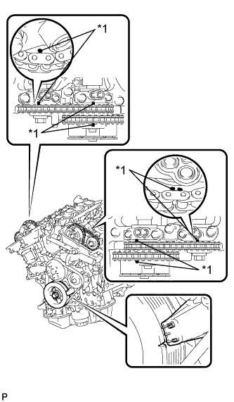
CHECK VALVE TIMING (CHECK FOR LOOSE OR JUMPED TEETH ON TIMING CHAIN)
-
Remove the cylinder head cover sub-assemblies RH and LH.
-
Turn the crankshaft to align the timing marks of the crankshaft.
-
Align the notch of the crankshaft pulley to the "0" position.
-
Check if the timing marks of the camshaft pulley and camshaft bearing cap align.
-
Turn the crankshaft clockwise 360° if the timing marks do not align. Check if they align once again.
OK The timing marks of the camshaft pulley and the camshaft bearing cap align when the notch of the crankshaft pulley is in the "0" position. Text in Illustration *1 Timing Mark -
Reinstall the cylinder head cover sub-assemblies RH and LH.
NG
ADJUST VALVE TIMING Click here
OK
-
-
INSPECT CAMSHAFT TIMING OIL CONTROL VALVE ASSEMBLY
-
Inspect the camshaft timing oil control valve assembly Click here.
NG
REPLACE CAMSHAFT TIMING OIL CONTROL VALVE ASSEMBLY Click here
OK
-
-
INSPECT OIL CONTROL VALVE FILTER AND OIL PIPE
-
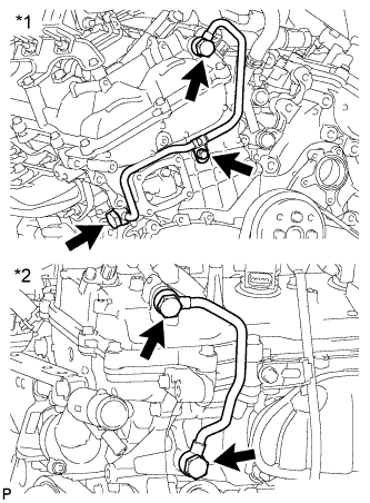
Text in Illustration *1 Bank 1 *2 Bank 2 Remove the No. 1 oil pipe or No. 2 oil pipe.
-
Remove the oil control valve filter RH or oil control valve filter LH.
-
Check that the oil control valve filter and oil pipe are not clogged.
OK The oil control valve filter and oil pipe are not clogged. -
Reinstall the oil control valve filter RH or oil control valve filter LH.
-
Reinstall the No. 1 oil pipe or No. 2 oil pipe.
NG
REPLACE OIL PIPE OR OIL CONTROL VALVE FILTER Click here
OK
-
-
REPLACE CAMSHAFT TIMING GEAR ASSEMBLY
-
Replace the camshaft timing gear assembly (bank 1 or bank 2) Click here.
NEXT
-
-
CHECK WHETHER DTC OUTPUT RECURS
-
Connect the intelligent tester to the DLC3.
-
Turn the power switch on (IG).
-
Turn the tester on.
-
Clear the DTCs Click here.
-
Turn the power switch off.
-
Turn the power switch on (IG) and turn the tester on.
-
Put the engine in inspection mode Click here.
-
Start the engine and warm it up.
-
Drive the vehicle in accordance with the driving pattern described in the Confirmation Driving Pattern.
-
Enter the following menus: Powertrain / Engine and ECT / DTC / Pending.
-
Read the DTCs.
Result Result Proceed to DTC is not output A DTC P0016 or P0018 is output B
B
REPLACE ECM Click here
A
END
-