SFI SYSTEM (w/ EGR System), Diagnostic DTC:P2119

| DTC Code | DTC Name |
|---|---|
| P2119 | Throttle Actuator Control Throttle Body Range / Performance |
DESCRIPTION
The electronic throttle control system is composed of the throttle actuator, throttle position sensor, accelerator pedal position sensor, and ECM. The ECM operates the throttle actuator to regulate the throttle valve in response to driver inputs. The throttle position sensor detects the opening angle of the throttle valve, and provides the ECM with feedback so that the throttle valve can be appropriately controlled by the ECM.
| DTC No. | DTC Detection Condition | Trouble Area |
|---|---|---|
| P2119 | Throttle valve opening angle continues to vary greatly from the target opening angle (1 trip detection logic) |
|
FAIL-SAFE
When this DTC, as well as other DTCs relating to electronic throttle control system malfunctions is stored, the ECM enters fail-safe mode. During fail-safe mode, the ECM cuts the current to the throttle actuator, and the throttle valve is returned to a 6° throttle angle by the return spring. The ECM then adjusts the engine output by controlling the fuel injection (intermittent fuel-cut) and ignition timing, in accordance with the accelerator pedal opening angle, to allow the vehicle to continue running at a minimal speed. If the accelerator pedal is depressed firmly and gently, the vehicle can be driven slowly. Fail-safe mode continues until a pass condition is detected, and the power switch is then turned off.
WIRING DIAGRAM
Refer to DTC P2102 Click here.
INSPECTION PROCEDURE
Tech Tips
Read freeze frame data using the intelligent tester. The ECM records vehicle and driving condition information as freeze frame data the moment a DTC is stored. When troubleshooting, freeze frame data can help determine if the vehicle was moving or stationary, if the engine was warmed up or not, if the air fuel ratio was lean or rich, and other data from the time the malfunction occurred.
PROCEDURE
-
CHECK ANY OTHER DTCS OUTPUT (IN ADDITION TO DTC P2119)
-
Connect the intelligent tester to the DLC3.
-
Turn the power switch on (IG).
-
Turn the tester on.
-
Enter the following menus: Powertrain / Engine and ECT / DTC.
-
Read the DTCs.
Result Result Proceed to DTC P2119 is output A DTC P2119 and other DTCs are output B Tech Tips
If any DTCs other than P2119 are output, troubleshoot those DTCs first.
B 
GO TO DTC CHART Click here
A 
-
-
INSPECT THROTTLE WITH MOTOR BODY ASSEMBLY (RESISTANCE OF THROTTLE ACTUATOR)
-
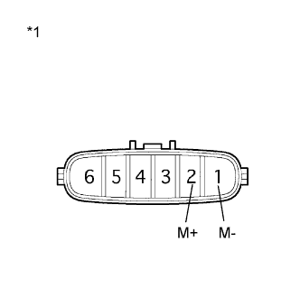
Text in Illustration *1 Component without harness connected
(Throttle with Motor Body Assembly)
Disconnect the throttle with motor body assembly connector.
-
Measure the resistance according to the value(s) in the table below.
Standard Resistance Tester Connection Condition Specified Condition 2 (M+) - 1 (M-) 20°C (68°F) 0.3 to 100 Ω -
Reconnect the throttle with motor body assembly connector.
NG
REPLACE THROTTLE WITH MOTOR BODY ASSEMBLY Click here
OK
-
-
REPLACE ECM
-
Replace the ECM Click here.
NEXT
-
-
CHECK WHETHER DTC OUTPUT RECURS (DTC P2119)
-
Connect the intelligent tester to the DLC3.
-
Turn the power switch on (IG).
-
Turn the tester on.
-
Clear the DTCs Click here.
-
Put the engine in inspection mode Click here.
-
Allow the engine to idle for 15 seconds or more.
-
Fully depress and release the accelerator pedal several times quickly.
-
Enter the following menus: Powertrain / Engine and ECT / DTC.
-
Read the DTCs.
Tech Tips
The output voltage of the throttle position sensor can be checked using the tester. Variations in the output voltage indicate that the throttle actuator is in operation. To check the output voltage using the tester, enter the following menus: Powertrain / Engine and ECT / Data List / All Data / Throttle Position No. 1.
Result Result Proceed to DTC is not output A DTC P2119 is output B
B
REPLACE THROTTLE WITH MOTOR BODY ASSEMBLY Click here
A 
END
-