SFI SYSTEM (w/ EGR System), Diagnostic DTC:P0120, P0121, P0122, P0123, P0220, P0222, P0223, P2135

| DTC Code | DTC Name |
|---|---|
| P0120 | Throttle / Pedal Position Sensor / Switch "A" Circuit Malfunction |
| P0121 | Throttle / Pedal Position Sensor / Switch "A" Circuit Range / Performance Problem |
| P0122 | Throttle / Pedal Position Sensor / Switch "A" Circuit Low Input |
| P0123 | Throttle / Pedal Position Sensor / Switch "A" Circuit High Input |
| P0220 | Throttle / Pedal Position Sensor / Switch "B" Circuit |
| P0222 | Throttle / Pedal Position Sensor / Switch "B" Circuit Low Input |
| P0223 | Throttle / Pedal Position Sensor / Switch "B" Circuit High Input |
| P2135 | Throttle / Pedal Position Sensor / Switch "A" / "B" Voltage Correlation |
DESCRIPTION
Tech Tips
-
These DTCs relate to the throttle position sensor.
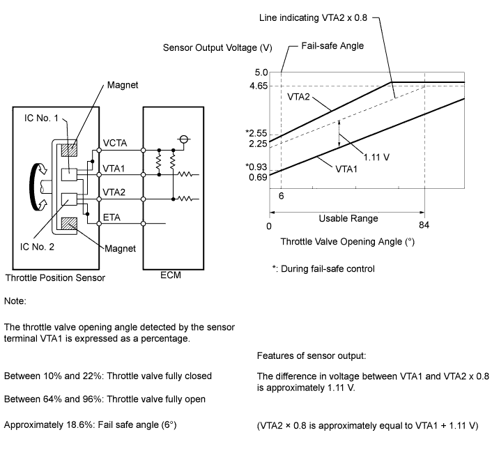
The throttle position sensor is mounted on the throttle with motor body assembly, and detects the opening angle of the throttle valve. This sensor is a non-contact type sensor. It uses hall-effect elements in order to yield accurate signals even in extreme driving conditions, such as at high speeds as well as very low speeds.
The throttle position sensor has 2 sensor circuits, each of which transmits a signal, VTA1 and VTA2. VTA1 is used to detect the throttle valve angle and VTA2 is used to detect malfunctions in VTA1. The sensor signal voltages vary between 0 V and 5 V in proportion to the throttle valve opening angle, and are transmitted to the VTA1 terminals of the ECM.
As the valve closes, the sensor output voltage decreases and as the valve opens, the sensor output voltage increases. The ECM calculates the throttle valve opening angle according to these signals and controls the throttle actuator in response to driver inputs. These signals are also used in calculations such as air fuel ratio correction, power increase correction and fuel-cut control.
| DTC No. | DTC Detection Condition | Trouble Area |
|---|---|---|
| P0120 | The output voltage of VTA1 quickly fluctuates beyond lower and upper malfunction thresholds for 2 seconds (1 trip detection logic) |
|
| P0121 | The difference between the VTA1 and VTA2 voltages is below 0.8 V or higher than 1.6 V for 2 seconds (1 trip detection logic) |
|
| P0122 | The output voltage of VTA1 is 0.2 V or less for 2 seconds (1 trip detection logic) |
|
| P0123 | The output voltage of VTA1 is 4.54 V or higher for 2 seconds (1 trip detection logic) |
|
| P0220 | The output voltage of VTA2 quickly fluctuates beyond the lower and upper malfunction thresholds for 2 seconds (1 trip detection logic) |
|
| P0222 | The output voltage of VTA2 is 1.75 V or less for 2 seconds (1 trip detection logic) |
|
| P0223 | The output voltage of VTA2 is 4.8 V or higher, and VTA1 is between 0.2 V and 2.02 V, for 2 seconds (1 trip detection logic) |
|
| P2135 | Either of the following conditions is met (1 trip detection logic): (a) The difference between the output voltages of VTA1 and VTA2 is 0.02 V or less for 0.5 seconds (b) The output voltage of VTA1 is 0.2 V or less, and VTA2 is 1.75 V or less, for 0.4 seconds |
|
CONFIRMATION DRIVING PATTERN
-
Connect the intelligent tester to the DLC3.
-
Turn the power switch on (IG).
-
Turn the tester on.
-
Clear the DTCs (even if no DTCs are stored, perform the clear DTC procedure) Click here.
-
Turn the power switch off.
-
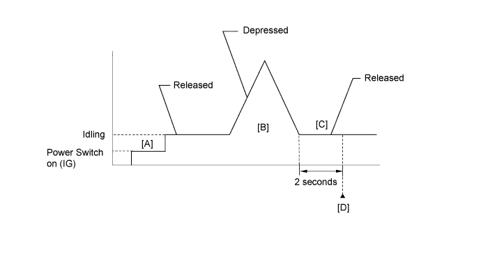
Turn the power switch on (IG) and turn the tester on [A].
-
Put the engine in inspection mode Click here.
-
Start the engine.
-
With the vehicle stationary, fully depress and release the accelerator pedal [B].
-
Idle the engine for 2 seconds or more [C].
-
Enter the following menus: Powertrain / Engine and ECT / Utility / All Readiness.
-
Input the DTC: P0120, P0121, P0122, P0123, P0220, P0222, P0223 or P2135.
-
Check the DTC judgment result [D].
Tester Display Description NORMAL
-
DTC judgment completed
-
System normal
ABNORMAL
-
DTC judgment completed
-
System abnormal
INCOMPLETE
-
DTC judgment not completed
-
Perform driving pattern after confirming DTC enabling conditions
UNKNOWN
-
Unable to perform DTC judgment
-
Number of DTCs which do not fulfill DTC preconditions has reached ECU's memory limit
Tech Tips
-
If the judgment result shows ABNORMAL, the system has a malfunction.
-
If the judgment result shows INCOMPLETE or UNKNOWN, perform steps [B] and [D] again.
-
FAIL-SAFE
When any of these DTCs, as well as other DTCs relating to electronic throttle control system malfunctions are set, the ECM enters fail-safe mode. During fail-safe mode, the ECM cuts the current to the throttle actuator, and the throttle valve is returned to a 6° throttle angle by the return spring. The ECM then adjusts the engine output by controlling the fuel injection (intermittent fuel-cut) and ignition timing, in accordance with the accelerator pedal opening angle, to allow the vehicle to continue at a minimal speed. If the accelerator pedal is depressed firmly and gently, the vehicle can be driven slowly.
Fail-safe mode continues until a pass condition is detected, and the power switch is then turned off.
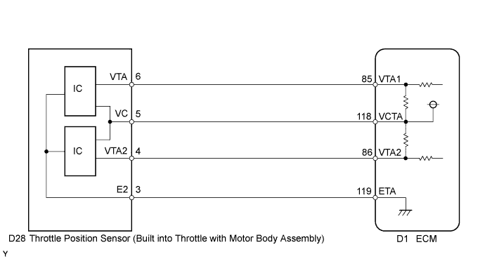
WIRING DIAGRAM
INSPECTION PROCEDURE
Tech Tips
-
DTC P0121 is stored when the voltages output from VTA1 and VTA2 are not consistent with the characteristics of the sensors. Therefore, check the Freeze Frame Data when this DTC is output. Use the following formula to confirm relative fluctuations in voltage.
Features of sensor output VTA2 x 0.8 is approximately equal to VTA1 + 1.11 V VTA1: Throttle Position No. 1 VTA2: Throttle position No. 2 -
If DTC P0121 is output, proceed to "Check Harness And Connector (Throttle Position Sensor - ECM)".
-
Read freeze frame data using the intelligent tester. The ECM records vehicle and driving condition information as freeze frame data the moment a DTC is stored. When troubleshooting, freeze frame data can help determine if the vehicle was moving or stationary, if the engine was warmed up or not, if the air fuel ratio was lean or rich, and other data from the time the malfunction occurred.
PROCEDURE
-
CHECK HARNESS AND CONNECTOR (THROTTLE POSITION SENSOR - ECM)
-
Disconnect the throttle with motor body assembly connector.
-
Disconnect the ECM connector.
-
Measure the resistance according to the value(s) in the table below.
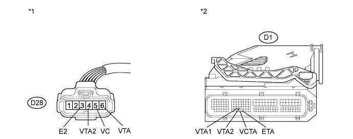
Standard Resistance (Check for Open) Tester Connection Condition Specified Condition D28-5 (VC) - D1-118 (VCTA) Always Below 1 Ω D28-6 (VTA) - D1-85 (VTA1) Always Below 1 Ω D28-4 (VTA2) - D1-86 (VTA2) Always Below 1 Ω D28-3 (E2) - D1-119 (ETA) Always Below 1 Ω Standard Resistance (Check for Short) Tester Connection Condition Specified Condition D28-5 (VC) or D1-118 (VCTA) - Body ground Always 10 kΩ or higher D28-6 (VTA) or D1-85 (VTA1) - Body ground Always 10 kΩ or higher D28-4 (VTA2) or D1-86 (VTA2) - Body ground Always 10 kΩ or higher Text in Illustration *1 Front view of wire harness connector
(to Throttle Position Sensor)
*2 Front view of wire harness connector
(to ECM)
-
Reconnect the ECM connector.
-
Reconnect the throttle with motor body assembly connector.
NG 
REPAIR OR REPLACE HARNESS OR CONNECTOR (THROTTLE POSITION SENSOR - ECM)
OK 
-
-
INSPECT ECM (VC VOLTAGE)
-
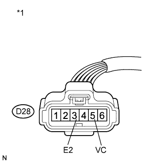
Text in Illustration *1 Front view of wire harness connector
(to Throttle Position Sensor)
Disconnect the throttle with motor body assembly connector.
-
Turn the power switch on (IG).
-
Measure the voltage according to the value(s) in the table below.
Standard Voltage Tester Connection Switch Condition Specified Condition D28-5 (VC) - D28-3 (E2) Power switch on (IG) 4.5 to 5.5 V -
Reconnect the throttle with motor body assembly connector.
NG
REPLACE ECM Click here
OK
-
-
REPLACE THROTTLE WITH MOTOR BODY ASSEMBLY
-
Replace the throttle with motor body assembly Click here.
NEXT
-
-
CHECK WHETHER DTC OUTPUT RECURS (THROTTLE POSITION SENSOR DTCS)
-
Connect the intelligent tester to the DLC3.
-
Turn the power switch on (IG).
-
Turn the tester on.
-
Clear the DTCs Click here.
-
Put the engine in inspection mode Click here.
-
Start the engine.
-
Drive the vehicle in accordance with the driving pattern described in the Confirmation Driving Pattern.
-
Enter the following menus: Powertrain / Engine and ECT / DTC.
-
Read the DTCs.
Result Result Proceed to DTC P0120, P0121, P0122, P0123, P0220, P0222, P0223, and/or P2135 are output A DTC is not output B
B
END
A 
REPLACE ECM Click here
-