SFI SYSTEM (w/ EGR System), Diagnostic DTC:P0403

| DTC Code | DTC Name |
|---|---|
| P0403 | Exhaust Gas Recirculation Control Circuit |
DESCRIPTION
Refer to DTC P0401 Click here.
| DTC No. | DTC Detection Condition | Trouble Area |
|---|---|---|
| P0403 | Open or short in EGR valve circuit (1 trip detection logic) |
|
Tech Tips
DTC P0403 is set when the power switch is on (IG).
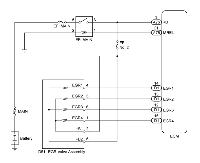
WIRING DIAGRAM
INSPECTION PROCEDURE
Tech Tips
Read freeze frame data using an intelligent tester. The ECM records vehicle and driving condition information as freeze frame data the moment a DTC is stored. When troubleshooting, freeze frame data can help determine if the vehicle was moving or stationary, if the engine was warmed up or not, if the air fuel ratio was lean or rich, and other data from the time the malfunction occurred.
PROCEDURE
-
PERFORM ACTIVE TEST USING INTELLIGENT TESTER (OPERATE EGR VALVE)
-
Connect the intelligent tester to the DLC3.
-
Turn the power switch on (IG).
-
Turn the tester on.
-
Put the engine in inspection mode (maintenance mode) Click here.
-
Start the engine and warm it up until the engine coolant temperature reaches 75°C (167°F) or higher.
Tech Tips
The A/C switch and all accessory switches should be off.
-
Enter the following menus: Powertrain / Engine and ECT / Active Test / Control the EGR Step Position / Data List / All Data / Throttle Idle Position and MAP.
-
Confirm that the Throttle Idle Position is ON and check the MAP value in the Data List while performing the Active Test.
Note
-
Do not leave the EGR valve open for 10 seconds or more during the Active Test.
-
Be sure to return the EGR valve to step 0 when the Active Test is completed.
-
Do not open the EGR valve 30 steps or more during the Active Test.
OK MAP change in response to EGR step position when Throttle Idle Position is ON in Data List. Standard - EGR Step Position (Active Test) 0 Steps 0 to 30 Steps MAP
(Data List)
(EGR valve is fully closed) MAP value is at least +10 kPa (75 mmHg) higher than when EGR valve is fully closed Tech Tips
-
While performing the Active Test, if the increase in the value of MAP is small, the EGR valve assembly may be a malfunctioning.
-
Even if the EGR valve assembly is malfunctioning, rough idling or an increase in the value of MAP may occur while performing the Active Test. However, the amount that the value of MAP increases will be smaller than normal.
-
NG 
INSPECT EGR VALVE ASSEMBLY Click here
OK 
CHECK FOR INTERMITTENT PROBLEMS Click here
-
-
INSPECT EGR VALVE ASSEMBLY
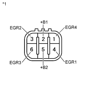
Text in Illustration *1 Component without harness connected
(EGR Valve Assembly)
-
Disconnect the EGR valve assembly connector.
-
Measure the resistance according to the value(s) in the table below.
Standard Resistance Tester Connection Condition Specified Condition 2 (+B1) - 1 (EGR4) 20°C (68°F) 18 to 22 Ω 2 (+B1) - 3 (EGR2) 20°C (68°F) 18 to 22 Ω 5 (+B2) - 4 (EGR1) 20°C (68°F) 18 to 22 Ω 5 (+B2) - 6 (EGR3) 20°C (68°F) 18 to 22 Ω -
Reconnect the EGR valve assembly connector.
NG 
REPLACE EGR VALVE ASSEMBLY Click here
OK 
-
-
INSPECT EGR VALVE ASSEMBLY (+B1 OR +B2 VOLTAGE)
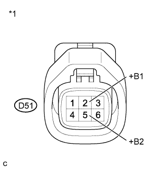
Text in Illustration *1 Front view of wire harness connector
(to EGR Valve Assembly)
-
Disconnect the EGR valve assembly connector.
-
Turn the power switch on (IG).
-
Measure the voltage according to the value(s) in the table below.
Standard Voltage Tester Connection Switch Condition Specified Condition D51-2 (+B1) - Body ground Power switch on (IG) 11 to 14 V D51-5 (+B2) - Body ground Power switch on (IG) 11 to 14 V -
Reconnect the EGR valve assembly connector.
NG
REPAIR OR REPLACE HARNESS OR CONNECTOR (EGR VALVE ASSEMBLY - EFI MAIN RELAY)
OK
-
-
CHECK HARNESS AND CONNECTOR (ECM - EGR VALVE ASSEMBLY)
-
Disconnect the EGR valve assembly connector.
-
Disconnect the ECM connector.
-
Measure the resistance according to the value(s) in the table below.
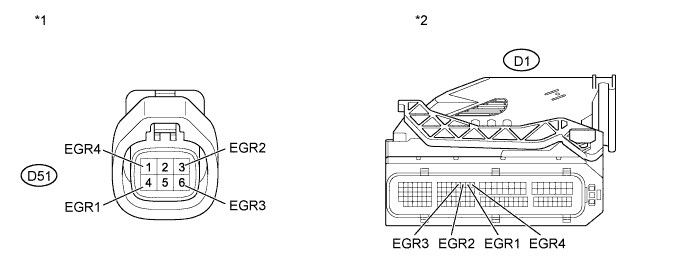
Standard Resistance (Check for Open) Tester Connection Condition Specified Condition D1-14 (EGR1) - D51-4 (EGR1) Always Below 1 Ω D1-13 (EGR2) - D51-3 (EGR2) Always Below 1 Ω D1-12 (EGR3) - D51-6 (EGR3) Always Below 1 Ω D1-15 (EGR4) - D51-1 (EGR4) Always Below 1 Ω Standard Resistance (Check for Short) Tester Connection Condition Specified Condition D1-14 (EGR1) or D51-4 (EGR1) - Body ground Always 10 kΩ or higher D1-13 (EGR2) or D51-3 (EGR2) - Body ground Always 10 kΩ or higher D1-12 (EGR3) or D51-6 (EGR3) - Body ground Always 10 kΩ or higher D1-15 (EGR4) or D51-1 (EGR4) - Body ground Always 10 kΩ or higher Text in Illustration *1 Front view of wire harness connector
(to EGR Valve Assembly)
*2 Front view of wire harness connector
(to ECM)
-
Reconnect the EGR valve assembly connector.
-
Reconnect the ECM connector.
NG
REPAIR OR REPLACE HARNESS OR CONNECTOR (ECM - EGR VALVE ASSEMBLY)
OK
REPLACE ECM Click here
-