SFI SYSTEM (w/ EGR System), Diagnostic DTC:P0037, P0038, P0057, P0058, P102D, P105D

| DTC Code | DTC Name |
|---|---|
| P0037 | Oxygen Sensor Heater Control Circuit Low (Bank 1 Sensor 2) |
| P0038 | Oxygen Sensor Heater Control Circuit High (Bank 1 Sensor 2) |
| P0057 | Oxygen Sensor Heater Control Circuit Low (Bank 2 Sensor 2) |
| P0058 | Oxygen Sensor Heater Control Circuit High (Bank 2 Sensor 2) |
| P102D | O2 Sensor Heater Circuit Performance Bank 1 Sensor 2 Stuck ON |
| P105D | O2 Sensor Heater Circuit Performance Bank 2 Sensor 2 Stuck ON |
DESCRIPTION
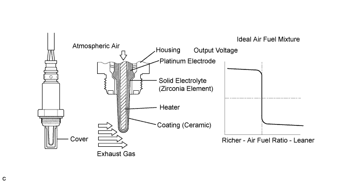
A three-way catalytic converter is used in order to convert the carbon monoxide (CO), hydrocarbon (HC), and nitrogen oxide (NOx) into less harmful substances. To allow the three-way catalytic converter to function effectively, it is necessary to keep the air fuel ratio of the engine near the stoichiometric air fuel ratio. For the purpose of helping the ECM to deliver accurate air fuel ratio control, a heated oxygen sensor is used.
The heated oxygen sensor is located behind the three-way catalytic converter, and detects the oxygen concentration in the exhaust gas. Since the sensor is integrated with the heater that heats the sensing portion, it is possible to detect the oxygen concentration even when the intake air volume is low (the exhaust gas temperature is low).
When the air fuel ratio becomes lean, the oxygen concentration in the exhaust gas becomes rich. The heated oxygen sensor informs the ECM that the post-three-way catalytic converter air fuel ratio is lean (low voltage, i.e. less than 0.45 V).
Conversely, when the air fuel ratio is richer than the stoichiometric air fuel level, the oxygen concentration in the exhaust gas becomes lean. The heated oxygen sensor informs the ECM that the post-three-way catalytic converter air fuel ratio is rich (high voltage, i.e. more than 0.45 V). The heated oxygen sensor has the property of changing its output voltage drastically when the air fuel ratio is close to the stoichiometric level.
The ECM uses the supplementary information from the heated oxygen sensor to determine whether the air fuel ratio after the three-way catalytic converter is rich or lean, and adjusts the fuel injection time accordingly. Thus, if the heated oxygen sensor is working improperly due to internal malfunctions, the ECM is unable to compensate for deviations in the primary air fuel ratio control.
Tech Tips
-
Sensor 2 refers to the sensor mounted behind the three-way catalytic converter and located far from the engine assembly.
-
When any of these DTCs are set, the ECM enters fail-safe mode. The ECM turns off the heated oxygen sensor heater in fail-safe mode. Fail-safe mode continues until the power switch is turned off.
-
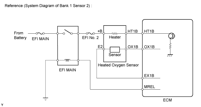
The ECM provides a pulse width modulated control circuit to adjust the current through the heater. The heated oxygen sensor heater circuit uses a relay on the +B side of the circuit.
| DTC No. | DTC Detection Condition | Trouble Area |
|---|---|---|
| P0037 P0057 |
Heated oxygen sensor heater (bank 1, 2 sensor 2) current is less than 0.3 A (1 trip detection logic) |
|
| P0038 P0058 |
Heated oxygen sensor heater (bank 1, 2 sensor 2) current fail (1 trip detection logic) |
|
| P102D P105D |
Heated oxygen sensor heater (bank 1, 2 sensor 2) current more than the specified value while the heater is not operating (1 trip detection logic) |
ECM |
Tech Tips
-
Bank 1 refers to the bank that includes cylinder No. 1.
-
Bank 2 refers to the bank that does not include cylinder No. 1.
-
Sensor 1 refers to the sensor closest to the engine assembly.
-
Sensor 2 refers to the sensor farthest away from the engine assembly.
WIRING DIAGRAM
Refer to DTC P0136 Click here.
INSPECTION PROCEDURE
Note
Inspect the fuses for circuits related to this system before performing the following inspection procedure.
Tech Tips
Read freeze frame data using the intelligent tester. The ECM records vehicle and driving condition information as freeze frame data the moment a DTC is stored. When troubleshooting, freeze frame data can help determine if the vehicle was moving or stationary, if the engine was warmed up or not, if the air fuel ratio was lean or rich, and other data from the time the malfunction occurred.
PROCEDURE
-
INSPECT HEATED OXYGEN SENSOR (HEATER RESISTANCE)
-
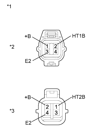
Text in Illustration *1 Component without harness connected
(Heated Oxygen Sensor)
*2 Bank 1 *3 Bank 2 Disconnect the heated oxygen sensor connector.
-
Measure the resistance according to the value(s) in the table below.
Standard Resistance Tester Connection Condition Specified Condition 2 (HT1B) - 1 (+B) 20°C (68°F) 11 to 16 Ω 2 (HT1B) - 3 (E2) Always 10 kΩ or higher 1 (HT2B) - 2 (+B) 20°C (68°F) 11 to 16 Ω 1 (HT2B) - 4 (E2) Always 10 kΩ or higher -
Reconnect the heated oxygen sensor connector.
NG 
REPLACE HEATED OXYGEN SENSOR Click here
OK 
-
-
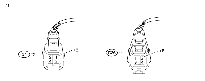
CHECK TERMINAL VOLTAGE (+B OF HEATED OXYGEN SENSOR)
-
Disconnect the heated oxygen sensor connector.
-
Turn the power switch on (IG).
-
Measure the voltage according to the value(s) in the table below.
Standard Voltage Tester Connection Switch Condition Specified Condition S1-1 (+B) - Body ground Power switch on (IG) 11 to 14 V D36-2 (+B) - Body ground Power switch on (IG) 11 to 14 V Text in Illustration *1 Front view of wire harness connector
(to Heated Oxygen Sensor)
*2 Bank 1 *3 Bank 2 - - -
Reconnect the heated oxygen sensor connector.
NG
REPAIR OR REPLACE HARNESS OR CONNECTOR (HEATED OXYGEN SENSOR - EFI MAIN RELAY)
OK
-
-
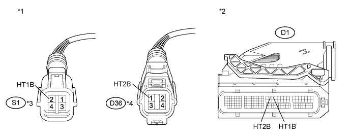
CHECK HARNESS AND CONNECTOR (HEATED OXYGEN SENSOR - ECM)
-
Disconnect the heated oxygen sensor connector.
-
Disconnect the ECM connector.
-
Measure the resistance according to the value(s) in the table below.
Standard Resistance (Check for Open) Tester Connection Condition Specified Condition S1-2 (HT1B) - D1-18 (HT1B) Always Below 1 Ω D36-1 (HT2B) - D1-17 (HT2B) Always Below 1 Ω Standard Resistance (Check for Short) Tester Connection Condition Specified Condition S1-2 (HT1B) or D1-18 (HT1B) - Body ground Always 10 kΩ or higher D36-1 (HT2B) or D1-17 (HT2B) - Body ground Always 10 kΩ or higher Text in Illustration *1 Front view of wire harness connector
(to Heated Oxygen Sensor)
*2 Front view of wire harness connector
(to ECM)
*3 Bank 1 *4 Bank 2 -
Reconnect the heated oxygen sensor connector.
-
Reconnect the ECM connector.
NG
REPAIR OR REPLACE HARNESS OR CONNECTOR (HEATED OXYGEN SENSOR - ECM)
OK 
REPLACE ECM Click here
-