REPAIR INSTRUCTION INITIALIZATION
-
PROCEDURES NECESSARY WHEN BATTERY TERMINAL IS DISCONNECTED/RECONNECTED
Necessary Procedures Procedure Details Effect / Inoperative Function When Necessary Procedures are not Performed Note Reset back door close position Fully close the back door to turn off the courtesy switch.
-
Power back door function
-
Back door closer function
-
If the back door is closed when disconnecting the cable from the battery terminal, it is not necessary to reset it.
-
The power back door ECU controls the locked or unlocked state of the back door based on its memory. If the connector for the power back door ECU is disconnected and reconnected, the back door will need to be unlocked before it can be operated.
Correct the steering angle neutral point Fully turn the steering wheel to the right and left on the flat ground.
-
Parking assist monitor system
-
Side monitor system
When "System initializing" is displayed on the multi-display, perform this procedure. Note
After the power switch is turned off, the display and navigation module display (HDD navigation system) records various types of memory and settings. As a result, after turning the power switch off, make sure to wait for the time specified in the following table before disconnecting the cable from the negative (-) battery terminal.
Waiting Time before Disconnecting Cable from Negative (-) Battery Terminal Specification Waiting Time w/o Telematics transceiver 60 sec. w/ Telematics transceiver 120 sec. -
-
PROCEDURES NECESSARY WHEN ECU OR OTHER PARTS ARE REPLACED
Replacement Part Necessary Procedure Effect / Inoperative Function when Necessary Procedures are not Performed Note Millimeter wave radar sensor assembly Adjust millimeter wave radar sensor assembly (Dynamic radar cruise control system)
-
Dynamic radar cruise control system
-
Pre-crash safety system
- Suspension control ECU
-
Registration of vehicle identification information
-
Vehicle height offset calibration
-
Vehicle specific control cannot be performed
-
Vehicle height sensor data may be affected due to installation position, or vehicle height recognition may be erroneous
- Height control sensor Vehicle height offset calibration Vehicle height sensor data may be affected due to installation position, or vehicle height recognition may be erroneous - Skid control ECU
-
Initialization and calibration of the linear solenoid valve
-
Yaw rate and acceleration sensor zero point calibration
-
ABS warning light illumination
-
Slip indicator light illumination
-
Brake warning light / yellow (minor malfunction) illumination
-
VSC disabled or malfunctioning
- Brake actuator assembly
-
Bleed air
-
Clearing stored linear solenoid valve calibration data
-
Initialization and calibration of the linear solenoid valve
Brake does not operate properly -
-
Brake pedal stroke sensor
-
Brake pedal
-
Inspection and adjustment of brake pedal height
-
Clearing stored linear solenoid valve calibration data
-
Initialization and calibration of the linear solenoid valve
-
ABS warning light illumination
-
Slip indicator light illumination
-
Brake warning light / yellow (minor malfunction) illumination
-
VSC disabled or malfunctioning
- Yaw rate and acceleration sensor
-
Clearing zero point calibration data
-
Yaw rate and acceleration sensor zero point calibration
-
ABS warning light illumination
-
Slip indicator light illumination
-
Brake warning light / yellow (minor malfunction) illumination
-
VSC disabled or malfunctioning
-
Theft Deterrent System (Tilt sensor)
Necessary when wheel alignment adjustment. Power steering ECU Rotation angle sensor initialization and torque sensor zero point calibration
-
P/S warning light comes on
-
EPS control
DTC (C1515/C1525) will be stored when the power steering ECU is replaced. Steering column Rotation angle sensor initialization and torque sensor zero point calibration Steering effort is different between turning steering wheel to left and right -
-
Display and navigation module display *1
-
Telematics transceiver *1
Vehicle contract setting
-
G-BOOK service
-
Emergency call service
-
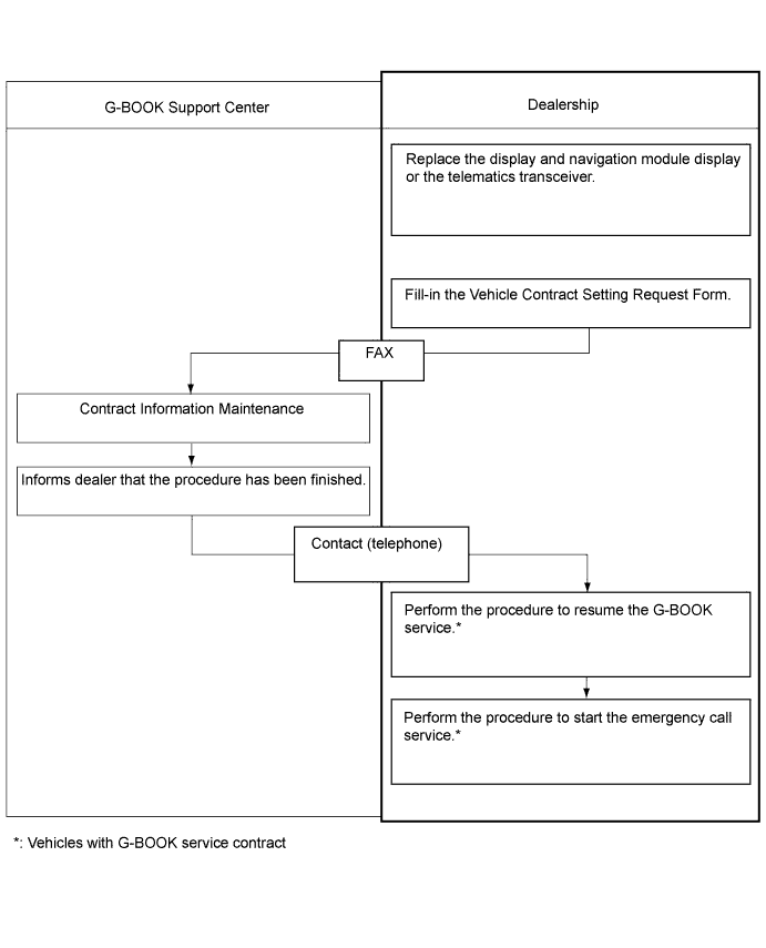
If the display and navigation module display or telematics transceiver is replaced on vehicles that do not have a contract for the G-BOOK service, perform the vehicle contract setting.
-
If the display and navigation module display or telematics transceiver is replaced on vehicles that have a contract for the G-BOOK service, perform the vehicle contract setting and the procedure to resume the G-BOOK service and to start the emergency call service.
Hard disk drive*1 Download necessary data Some G-BOOK service content will be unavailable. - Spiral with sensor cable sub-assembly
-
Correct steering angle neutral point
-
Steering angle setting
-
Parking assist monitor system
-
Side monitor system
- Parking assist ECU Parking assist ECU initialization
-
Parking assist monitor system
-
Side monitor system
- Rear television camera Rear television camera optical axis (Camera position setting) Parking assist monitor system Necessary when vehicle height changes due to replacement of the suspension or tire, etc.
-
Side television camera
-
Outer rear view mirror assembly (passenger side)
Side television camera optical axis (Camera position setting) Side monitor system Necessary when vehicle height changes due to replacement of the suspension or tire, etc.
-
Certification ECU (smart key ECU assembly)
-
ID code box (immobiliser code ECU)
-
Steering lock ECU (steering lock actuator assembly)
-
Key
Code registration (Engine immobiliser system)
-
Wireless door lock control system
-
Entry and start system
-
Engine start
See the Service Bulletin for the registration method.
-
Roof sunshade ECU (sliding roof drive gear sub-assembly)
-
Roof sunshade
-
Sliding roof housing
Initializing roof sunshade ECU (pulse sensor initial position setting)
-
Automatic slide open/close function of roof sunshade
-
Jam protection function
Necessary when the roof sunshade ECU is removed and installed (not necessary when the roof sunshade ECU (sliding roof drive gear sub-assembly) is removed and installed together with the sliding roof housing).
-
Power window regulator motor
-
Door window regulator
Initialize power window control system
-
Automatic door glass open/ close function
-
Jam protection function
-
Operation function after power switch is turned off
-
Key-linked operation function
-
Wireless transmitter-linked operation
Necessary when the regulator is removed and installed.
-
Sliding roof ECU (sliding roof drive gear sub-assembly)
-
Sliding roof glass
-
Sliding roof housing
Initializing sliding roof ECU (pulse sensor initial position setting)
-
Automatic slide open/close and tilt up/down function of sliding roof
-
Jam protection function
-
Operation function after power switch is turned off
Necessary when the sliding roof ECU is removed and installed (not necessary when the sliding roof ECU (sliding roof drive gear sub-assembly) is removed and installed together with the sliding roof housing). AFS ECU (headlight swivel ECU assembly) Perform AFS ECU (headlight swivel ECU assembly) initialization
-
Headlight leveling function
-
AFS
- Rear height control sensor sub-assembly RH *2 Perform AFS ECU (headlight swivel ECU assembly) initialization Headlight leveling function
-
Necessary when the sensor is removed and installed
-
Necessary when vehicle height changes due to replacement of the suspension
-
Adjust the headlight aim after initializing the AFS ECU
-
*1: w/ G-BOOK system
-
*2: w/o air suspension system
-
-
ADJUST MILLIMETER WAVE RADAR SENSOR ASSEMBLY (Dynamic Radar Cruise Control System)
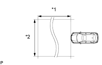
Text in Illustration *1 Approx. 10 m *2 Approx. 14 m CAUTION:
Exposure to radio frequency emissions is hazardous to your health. It is hazardous to be within 20 cm (7.87 in.) of the device's radio frequency aperture.
Note
-
This device complies with FCC radio frequency emission regulations.
-
Perform measurements on a level surface.
-
Make sure that no large pieces of metal are within a 10 m (32.8 ft.) x 14 m (45.9 ft.) area in front of the vehicle. If possible, the surrounding area should also be free of large metal objects.
-
Before adjusting the radar beam axis, prepare the vehicle as follows.
-
Check the tire pressure and adjust it if necessary.
-
Remove all excess weight from the vehicle (luggage, heavy objects, etc.).
-
-
w/ Air Suspension:
Adjust the vehicle's height to the standard height.
-
Check and adjust the vertical direction of the radar sensor.
-
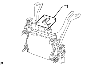
Text in Illustration *1 Level Remove dust, oil and foreign matter from the radar sensor's level rack.
-
Set a level on the radar sensor's level rack.
-
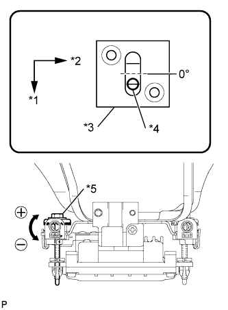
Text in Illustration *1 FR *2 LH *3 Level *4 Air Bubble *5 Bolt A Check that the level's air bubble is within the red frame.
If the bubble is not within the red frame, use a screwdriver to adjust bolt A until the level's air bubble is within the red frame.
Tech Tips
-
The adjustable range within the red frame of the level is +/-0.2°.
-
The target angle is +0.2° (upward angle of 0.2°).
-
-
-
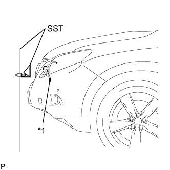
Text in Illustration *1 Millimeter Wave Radar Sensor Adjust the reflector height.
-
Adjust the reflector so that the center of SST reflector is the same height as the millimeter wave radar sensor.
- SST
- 09870-60000 ( 09870-60010 )
- 09870-60040
Tech Tips
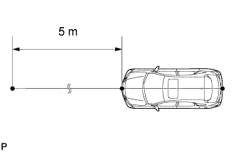
Prepare a 10 m (32.8 ft.) string, a string with a sharp-pointed weight (plumb bob), and a 5 m (16.4 ft.) tape measure.
-
-
Place the reflector.
-
Hang the string (with weight) from the center of the vehicle's rear emblem. Mark the vehicle's rear center point on the ground. Repeat for the front of the vehicle.
-
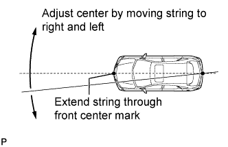
Set one end of the 10 m (32.8 ft.) string on the vehicle's rear center point. Run the string over the vehicle's front center point to a position 5 m (16.4 ft.) beyond the vehicle's front center point, as shown in the illustration. Mark the 5 m (16.4 ft.) position.
-
Using a tape measure, measure 15 mm (0.591 in.) to the right of the 5 m (16.4 ft.) position. Place the reflector at that position.
Note
Perform the operation as precisely as possible.
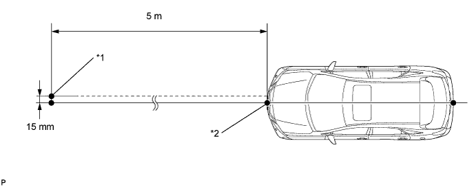
Text in Illustration *1 Reflector Placement Point *2 Millimeter Wave Radar Sensor Position
-
-
Check the radar beam axis.
-
Connect the intelligent tester to the DLC3.
-
Turn the power switch on (IG).
-
Turn the intelligent tester on, and turn the cruise control main switch on.
-
Select "Auto" from the intelligent tester display screen. *1
-
Select "Radar Cruise" from the display screen.
-
Select "Radar Cruise" from the display screen.
-
Select "Utility" from the display screen.
-
Select "Beam Axis Adjustment" from the display screen.
-
Follow the tester display, and select "Next".
CAUTION:
Do not come within 20 cm (7.87 in.) of the radar sensor.
Note
-
Turn the cruise control main switch on before pressing Next.
-
Make sure there is at least 20 cm (7.87 in.) between the radar sensor and any nearby individuals.
-
-
Check the following items on the laser cruise divergence data screen.
CAUTION:
While using the intelligent tester's beam axis adjustment mode, the actual direction and angle of the radar sensor may be different from the intelligent tester's data. In such a case, the deviation is displayed on the combination meter's multi-information display.
-
Confirm that the distance value is approximately 5 m (16.4 ft.).
Tech Tips
-
A value between 0.0 m (0.0 ft.) and 6.3 m (20.7 ft.) is indicated.
-
If the distance is 0.0 m (0.0 ft.), the sensor cannot detect the target. Reconfirm that there is no metal in the specified area in front of the vehicle (refer to the NOTICE at the beginning of this adjustment procedure).
-
-
Confirm that the left/right side value is between 0.0 m (0.0 ft.) and 6.3 m (20.7 ft.).
Tech Tips
If the distance is 0.0 m (0.0 ft.), the sensor cannot detect the target. Reconfirm that there is no metal in the specified area in front of the vehicle (refer to the NOTICE at the beginning of this adjustment procedure).
-
-
-
Check and adjust the horizontal direction of the radar sensor.
-
Check that the divergence of the radar beam axis is 0°.
If the axis is not as specified, use a screwdriver to adjust bolt B until the divergence of the radar beam axis is 0°.
-
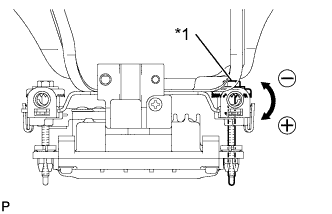
Text in Illustration *1 Bolt B Based on the measured divergence of the beam axis, turn and adjust bolt B for horizontal adjustment of the millimeter wave radar sensor using a screwdriver.
Tech Tips
-
If "LEFT SIDE: 1.0°" is displayed, the divergence is 1.0° in the left direction. Turn bolt B approximately 2.5 turns to the negative (-) side.
-
If the value does not change to 0°, it is possible that the sensor is aiming at something different. Reconfirm that there are no reflective materials in the surrounding area.
-
-
Select "Next". The driving learning value is automatically reset.
Tech Tips
A buzzer will sound for 10 seconds or more.
-
Disconnect the intelligent tester from the DLC3.
-
-
Recheck and readjust the vertical direction of the radar sensor.
-
Text in Illustration *1 Level Set a level on the radar sensor's level rack.
-
Text in Illustration *1 FR *2 LH *3 Level *4 Air Bubble *5 Bolt A Check that the level's air bubble is within the red frame.
If the bubble is not within the red frame, use a screwdriver to adjust bolt A until the level's air bubble is within the red frame.
Tech Tips
-
The adjustable range within the red frame is +/-0.2°.
-
The target angle is +0.2° (upward angle of 0.2°).
-
-
-
-
REGISTRATION OF VEHICLE IDENTIFICATION INFORMATION (Air Suspension System)
Note
-
The CAN communication system must be functioning normally.
-
Make sure that the power management control ECU is the correct type, normally functioning and correctly installed.
Tech Tips
-
If the suspension control ECU is replaced with a new one, perform registration of vehicle identification information.
-
Vehicle identification information is obtained automatically through CAN communication when in test mode.
-
Turn the power switch off.
-
Connect the intelligent tester to the DLC3.
-
Turn the power switch on (IG).
-
Turn the intelligent tester on.
-
Enter the following menus: Chassis / Air suspension / Utility / Signal Check.
-
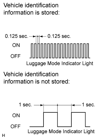
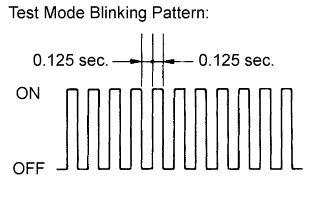
Confirm that the system is in test mode by checking that the luggage mode indicator light in the combination meter blinks at 0.125 second intervals (0.125 seconds on and 0.125 seconds off).
Tech Tips
-
When the vehicle identification information is stored, the luggage mode indicator light blinks at 0.125 second intervals (0.125 seconds on and 0.125 seconds off).
-
When vehicle identification information is not stored, the luggage mode indicator light blinks at 1 second intervals (1 second on and 1 second off).
-
-
-
VEHICLE HEIGHT OFFSET CALIBRATION (Air Suspension System)
Note
-
Make sure that the pressure of the tires is normal.
-
Make sure that the vehicle is empty.
-
Make sure that the parking brake is released and that the shift lever is in N. Ensure that the vehicle does not move at this time.
Tech Tips
If replacing the suspension control ECU and/or height control sensor, perform the vehicle height offset calibration.
-
ADJUST THE PRESSURE OF THE TIRES
-
Check the pressure of each tire and, if the value is not as specified, adjust it.
NEXT 
-
-
PERFORM VEHICLE HEIGHT INSPECTION
-
Stabilize the suspension by releasing the parking brake and bouncing the corners of the vehicle up and down.
-
Turn the power switch on (READY) and set the vehicle height in HI mode.
-
Check that the HI mode light blinks and then remains on, and that the vehicle height control operation has finished.
-
Set the vehicle height in N mode.
-
Check that the N mode light blinks and then remains on, and that the vehicle height control operation has finished.
-
Turn the power switch off.
-
Move the shift lever to N and move the vehicle forward and rearward.
-
Connect the intelligent tester to the DLC3.
-
Turn the power switch on (IG).
-
Turn the intelligent tester on.
-
Using the intelligent tester
Enter the following menus: Chassis / Air suspension / Data List. Then read and write the values for "After Height Adjust" and "Height Adjust" for each wheel.
Air Suspension System Tester Display Measurement Item/Range Normal Condition FR Height Adjust Display of vehicle height offset recorded value of front right wheel /
min.: -3276.8 mm (-129 in.)
max.: 3276.7 mm (129 in.)
- FL Height Adjust Display of vehicle height offset recorded value of front left wheel /
min.: -3276.8 mm (-129 in.)
max.: 3276.7 mm (129 in.)
- RR Height Adjust Display of vehicle height offset recorded value of rear right wheel /
min.: -3276.8 mm (-129 in.)
max.: 3276.7 mm (129 in.)
- RL Height Adjust Display of vehicle height offset recorded value of rear left wheel /
min.: -3276.8 mm (-129 in.)
max.: 3276.7 mm (129 in.)
- FR After Height Adjust Display of after-calibration vehicle height value of front right wheel /
min.: -3276.8 mm (-129 in.)
max.: 3276.7 mm (129 in.)
When vehicle height normal: 0 +/-20 mm (0 +/- 0.79 in.)
When vehicle height is changing: Varies based on vehicle height
After HEIGHT HIGH adjustment: 20 +/- 20 mm (0.79 +/- 0.79 in.)
FL After Height Adjust Display of after-calibration vehicle height value of front left wheel /
min.: -3276.8 mm (-129 in.)
max.: 3276.7 mm (129 in.)
When vehicle height normal: 0 +/-20 mm (0 +/- 0.79 in.)
When vehicle height is changing: Varies based on vehicle height
After HEIGHT HIGH adjustment: 20 +/- 20 mm (0.79 +/- 0.79 in.)
RR After Height Adjust Display of after-calibration vehicle height value of rear right wheel /
min.: -3276.8 mm (-129 in.)
max.: 3276.7 mm (129 in.)
When vehicle height normal: 0 +/-20 mm (0 +/- 0.79 in.)
When vehicle height is changing: Varies based on vehicle height
After HEIGHT HIGH adjustment: 20 +/- 20 mm (0.79 +/- 0.79 in.)
RL After Height Adjust Display of after-calibration vehicle height value of rear left wheel /
min.: -3276.8 mm (-129 in.)
max.: 3276.7 mm (129 in.)
When vehicle height normal: 0 +/-20 mm (0 +/- 0.79 in.)
When vehicle height is changing: Varies based on vehicle height
After HEIGHT HIGH adjustment: 20 +/- 20 mm (0.79 +/- 0.79 in.)
-
Turn the power switch off.
-
Inspect vehicle height and make a note of actual vehicle height.
-
Calculate the absolute value of "Height Adjust" + (standard vehicle height - measurement vehicle height - "After Height Adjust" ).
Standard Result Proceed to The absolute value of "Height Adjust" + (standard vehicle height - measurement vehicle height - "After Height Adjust" ) is more than 80 mm (3.15 in.). A The absolute value of "Height Adjust" + (standard vehicle height - measurement vehicle height - "After Height Adjust" ) is more than 10 (0.394 in.) mm but 80 mm (3.15 in.) or less. B The absolute value of "Height Adjust" + (standard vehicle height - measurement vehicle height - "After Height Adjust" ) is 10 mm (0.394 in.) or less. C Tech Tips
When performing automatic vehicle height adjustment using the intelligent tester, the maximum height adjustment is 80 mm (3.15 in.). If the absolute value of "Height Adjust" + (standard vehicle height - measurement vehicle height - "After Height Adjust" ) is more than 80 mm (3.15 in.), first adjust the height control sensor links as necessary until the vehicle height compensation value is less than 80 mm (3.15 in.).
B 
Go to step 4
C
END (VEHICLE HEIGHT ADJUSTMENT IS NOT NECESSARY)
A
-
-
PERFORM VEHICLE HEIGHT ADJUSTMENT USING HEIGHT CONTROL SENSOR LINK
-
Adjust vehicle height using the height control sensor links.
NEXT
-
-
PERFORM AUTOMATIC VEHICLE HEIGHT ADJUSTMENT USING INTELLIGENT TESTER
-
Turn the power switch on (READY) and set the vehicle height in HI mode.
-
Check that the HI mode light blinks and then remains on, and that the vehicle height control operation has finished.
-
Set the vehicle height in N mode.
-
Check that the N mode light blinks and then remains on, and that the vehicle height control operation has finished.
-
Turn the power switch off.
-
Connect the intelligent tester to the DLC3.
-
Turn the power switch on (IG).
-
Turn the intelligent tester on.
-
Enter the following menus: Chassis / Air suspension / Utility / Height Offset.
-
Following the intelligent tester display, input the values of "wheel of which the vehicle height sensor is to be adjusted", "actual measured vehicle height" and "vehicle height standard value (designed value)".
Tech Tips
With the power switch on (IG) and the power switch off, perform automatic adjustment.
-
Using the same procedure, perform "vehicle height sensor automatic adjustment" for the other height sensors.
NEXT
-
-
PERFORM VEHICLE HEIGHT INSPECTION
-
Turn the power switch on (READY) and set the vehicle height in HI mode.
-
Check that the HI mode light blinks and then remains on, and that the vehicle height control operation has finished.
-
Set the vehicle height in N mode.
-
Check that the N mode light blinks and then remains on, and that the vehicle height control operation has finished.
-
Check that the vehicle height is within the specification.
NEXT
END
-
-
-
PERFORM INITIALIZATION AND CALIBRATION OF LINEAR SOLENOID VALVE (When Using the Intelligent Tester) (Electronically Controlled Brake System)
-
Clear the stored linear solenoid valve calibration data.
-
Turn the power switch off.
-
Check that the steering wheel is centered.
-
Check that the shift lever is in P.
-
Connect the intelligent tester to the DLC3.
-
Turn the power switch on (IG).
-
Turn the intelligent tester on.
-
Select the skid control ECU to clear the linear solenoid valve calibration data using the intelligent tester. Enter the following menus: Chassis / ABS/VSC/TRC / Reset Memory.
-
Perform initialization and calibration of the linear solenoid valve.
-
Perform the zero point calibration of yaw rate and acceleration sensor.
-
-
Perform initialization and calibration of the linear solenoid valve.
-
Turn the power switch off.
-
Check that the steering wheel is centered.
-
Check that the shift lever is in P.
-
Connect the intelligent tester to the DLC3.
-
Turn the power switch on (IG) with the brake pedal released.
Note
-
If the linear solenoid valve offset learning is performed without turning the power switch on (IG), the learning process may not be completed properly because of insufficient auxiliary battery voltage.
-
When the linear solenoid valve offset learning is interrupted, or the learning process is performed with the shift lever not in P, DTC C1345 (Linear Solenoid Valve Offset Learning Undone) will be stored.
-
-
Turn the intelligent tester on.
-
Switch the skid control ECU to the Test Mode using the intelligent tester. Enter the following menus: Chassis / ABS/VSC/TRC / ECB* Utility / Linear Valve Offset.
*: Electronically Controlled Brake System
-
Leave the vehicle stationary without depressing the brake pedal for 1 or 2 minutes.
-
Check that the interval between blinks of the brake warning light / yellow (minor malfunction) changes from 1 second to 0.25 seconds.
Tech Tips
-
The time needed to complete initialization and calibration of the linear solenoid valve varies depending on auxiliary battery voltage.
-
The brake warning light / yellow (minor malfunction) blinks at 1 second intervals during initialization and calibration of the linear solenoid valve and changes to the Test Mode display.
-
The brake warning light / yellow (minor malfunction) blinks at 0.25 seconds intervals if the Test Mode is normal.
-
-
Check that DTC C1345 (Linear Solenoid Valve Offset Learning Undone) which indicates trouble with stroke sensor zero point learning is not output when the brake warning light / yellow (minor malfunction) changes to the Test Mode display upon initialization and calibration of the linear solenoid valve completion.
-
Enter the normal mode from the Test Mode following the intelligent tester directions.
Tech Tips
Refer to the intelligent tester operator's manual for further details.
-
-
-
PERFORM INITIALIZATION AND CALIBRATION OF LINEAR SOLENOID VALVE (When not Using the Intelligent Tester) (Electronically Controlled Brake System)
-
Clear the stored linear solenoid valve calibration data.
-
Turn the power switch off.
-
Check that the steering wheel is centered.
-
Check that the shift lever is in P.
-
Turn the power switch on (IG) with the brake pedal released.
-
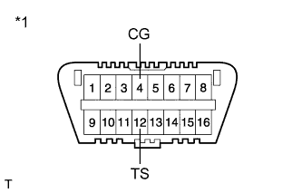
Text in Illustration *1 Front view of DLC3 Using SST, connect and disconnect terminals TS and CG of the DLC3 4 times or more within 8 seconds.
- SST
- 09843-18040
-
Check that no codes other than ABS code 42, VSC code 45 and electronically controlled brake system code 48, 66, or 95 are stored in the diagnostic system.
Tech Tips
The ABS warning, brake warning / yellow (minor malfunction) and slip indicator lights do not indicate a normal system code.
-
Remove SST from the terminals of the DLC3.
-
Perform initialization and calibration of the linear solenoid valve.
-
Perform the zero point calibration of yaw rate and acceleration sensor.
-
-
Perform initialization and calibration of the linear solenoid valve.
-
Turn the power switch off.
-
Check that the steering wheel is centered.
-
Check that the shift lever is in P.
-
Text in Illustration *1 Front view of DLC3 Using SST, connect terminals TS and CG of the DLC3.
- SST
- 09843-18040
-
Turn the power switch on (IG) with the brake pedal released.
Note
-
If the linear solenoid valve offset learning is performed without turning the power switch on (IG), the learning process may not be completed properly because of insufficient auxiliary battery voltage.
-
When the linear solenoid valve offset learning is interrupted, or the learning process is performed with the shift lever not in P, DTC 66 (Linear Solenoid Valve Offset Learning Undone) will be stored.
-
-
Leave the vehicle stationary without depressing the brake pedal for 1 or 2 minutes.
-
Check that the interval between blinks of the brake warning light / yellow (minor malfunction) changes from 1 second to 0.25 seconds.
Tech Tips
-
The time needed to complete initialization and calibration of the linear solenoid valve varies depending on the auxiliary battery voltage.
-
The brake warning light / yellow (minor malfunction) blinks at 1 second intervals during initialization and calibration of the linear solenoid valve and changes to the Test Mode display.
-
The brake warning light / yellow (minor malfunction) blinks at 0.25 seconds intervals if Test Mode is normal.
-
-
Check that DTC 66 (Linear Solenoid Valve Offset Learning Undone) which indicates trouble with stroke sensor zero point learning is not output when the brake warning light / yellow (minor malfunction) changes to the Test Mode display upon initialization and calibration of the linear solenoid valve completion.
-
Turn the power switch off and disconnect SST from the DLC3.
-
-
-
OBTAIN ZERO POINT OF YAW RATE AND ACCELERATION SENSOR (When Using the Intelligent Tester) (Electronically Controlled Brake System)
Note
-
While obtaining the zero points, keep the vehicle stationary and do not vibrate, tilt, move, or shake it. (Do not turn the power switch on (READY).)
-
Be sure to perform this procedure on a level surface (with an inclination of less than 1 degree).
-
Clear the zero point calibration data.
-
Turn the power switch off.
-
Check that the steering wheel is centered.
-
Check that the shift lever is in P.
-
Connect the intelligent tester to the DLC3.
-
Turn the power switch on (IG).
-
Turn the intelligent tester on.
-
Select the skid control ECU and clear the zero point calibration data using the intelligent tester. Enter the following menus: Chassis / ABS/VSC/TRC / Reset Memory.
-
Turn the power switch off.
Note
If the power switch is turned on (IG) for more than 15 seconds with the shift lever in P after the zero points of the yaw rate and acceleration sensor have been cleared, only the zero point of the yaw rate sensor will be stored. If the vehicle is driven under these conditions, the skid control ECU will store the zero point calibration for the acceleration sensor as not being completed. The skid control ECU will then also indicate this as a malfunction of the VSC system using the indicator light.
-
-
Perform the zero point calibration of the yaw rate and acceleration sensor.
-
Turn the power switch off.
-
Check that the steering wheel is centered.
-
Check that the shift lever is in P.
Note
DTCs C1210 (Zero Point Calibration of Yaw Rate Sensor Undone) and C1336 (Zero Point Calibration of Acceleration Sensor Undone) will be stored if the shift lever is not in P.
-
Connect the intelligent tester to the DLC3.
-
Turn the power switch on (IG).
-
Turn the intelligent tester on.
-
Switch the skid control ECU to Test Mode using the intelligent tester. Enter the following menus: Chassis / ABS/VSC/TRC / Test Mode.
-
After Test Mode has been entered, keep the vehicle stationary on a level surface for 2 seconds or more.
-
Check that the ABS warning, brake warning / yellow (minor malfunction) and slip indicator lights come on for several seconds and then blink in Test Mode.
Tech Tips
-
If the ABS warning, brake warning / yellow (minor malfunction) and slip indicator lights do not blink, perform zero point calibration again.
-
The zero point calibration is performed only once after the system enters Test Mode.
-
Calibration cannot be performed again until the stored data is cleared.
-
-
Turn the power switch off and disconnect the intelligent tester.
-
-
-
OBTAIN ZERO POINT OF YAW RATE AND ACCELERATION SENSOR (When not Using the Intelligent Tester) (Electronically Controlled Brake System)
Note
-
While obtaining the zero points, keep the vehicle stationary and do not vibrate, tilt, move, or shake it. (Do not turn the power switch on (READY).)
-
Be sure to perform this procedure on a level surface (with an inclination of less than 1 degree).
-
Clear the zero point calibration data.
-
Turn the power switch off.
-
Check that the steering wheel is centered.
-
Check that the shift lever is in P.
-
Turn the power switch on (IG).
-
Check that the initial check is completed.
-
Text in Illustration *1 Front view of DLC3 Using SST, connect and disconnect terminals TS and CG of the DLC3 4 times or more within 8 seconds.
- SST
- 09843-18040
-
Check that no codes other than ABS code 42, VSC code 45 and electronically controlled brake system code 48, 66, or 95 are stored in the diagnostic system.
Tech Tips
The ABS warning, brake warning / yellow (minor malfunction) and slip indicator lights do not indicate a normal system code.
Note
If the power switch is turned on (IG) for more than 15 seconds with the shift lever in P after the zero points of the yaw rate and acceleration sensor have been cleared, only the zero point of the yaw rate sensor will be stored. If the vehicle is driven under these conditions, the skid control ECU will store the zero point calibration for the acceleration sensor as not being completed. The skid control ECU will then also indicate this as a malfunction of the VSC system using the indicator light.
-
-
Perform the zero point calibration of the yaw rate and acceleration sensor.
-
Turn the power switch off.
-
Check that the steering wheel is centered.
-
Check that the shift lever is in P.
Note
DTCs 36 (Zero Point Calibration of Yaw Rate Sensor Undone) and 98 (Zero Point Calibration of Acceleration Sensor Undone) will be recorded if the shift lever is not in P.
-
Text in Illustration *1 Front view of DLC3 Using SST, connect terminals TS and CG of the DLC3.
- SST
- 09843-18040
-
Turn the power switch on (IG).
-
After Test Mode has been entered, keep the vehicle stationary on a level surface for 2 seconds or more.
-
Check that the ABS warning, brake warning / yellow (minor malfunction) and slip indicator lights come on for several seconds and then blink in Test Mode.
Tech Tips
-
If the ABS warning, brake warning / yellow (minor malfunction) and slip indicator lights do not blink, perform zero point calibration again.
-
The zero point calibration is performed only once after the system enters Test Mode.
-
Calibration cannot be performed again until the stored data is cleared.
-
-
Turn the power switch off and disconnect SST from the DLC3.
-
-
-
ROTATION ANGLE SENSOR INITIALIZATION AND TORQUE SENSOR ZERO POINT CALIBRATION (Power Steering System)
Note
Clear the rotation angle sensor calibration value, initialize the rotation angle sensor, and calibrate the torque sensor zero point if any of the following has occurred:
-
The power steering ECU has been replaced.
-
The steering column assembly has been replaced.
-
Steering effort differs between turning left and right.
-
Inspection before calibration
-
Turn the power switch off.
-
Connect the intelligent tester to the DLC3.
-
Turn the power switch on (IG).
-
Turn the intelligent tester on.
-
Calibrate the power steering ECU. Enter the following menus: Chassis / EMPS / Data List.
-
Check the values by referring to the table below.
EMPS Tester Display Measurement Item/Range Normal Condition Diagnostic Note IG Power Supply ECU power source voltage/
Min.: 0 V
Max.: 20.1531 V
10 to 14 V Power switch on (IG) Note
If the IG power supply voltage is 9 V or less, calibration cannot be performed. In this case, charge or replace the battery, and then perform calibration.
-
-
Rotation angle sensor calibration value clear, rotation angle sensor initialization, and torque sensor zero point calibration
Note
-
If DTC C1516 (Torque Sensor Zero Point Adjustment Incomplete) is stored, the torque sensor zero point cannot be calibrated. Clear the DTC before starting calibration.
-
If DTC C1526 (Rotation Angle Sensor Initialization Incomplete) is stored, the rotation angle sensor cannot be initialized. Clear the DTC before starting initialization.
-
Turn the power switch off.
-
Connect the intelligent tester to the DLC3.
-
Turn the power switch on (IG).
-
Turn the intelligent tester on.
-
Enter the following menus: Chassis / EMPS / Utility / Torque Sensor Adjustment.
Note
-
Center the steering wheel and align the front wheels straight ahead.
-
Do not turn the steering wheel sharply.
-
Do not touch the steering wheel during the torque sensor zero point calibration. (Wait for 3 seconds after the calibration.)
-
-
-
-
VEHICLE CONTRACT SETTING (G-BOOK System)
Tech Tips
-
If the display and navigation module display or the telematics transceiver is replaced on vehicles that do not have a contract for the G-BOOK service, perform the vehicle contract setting.
-
If the display and navigation module display or the telematics transceiver is replaced on vehicles that have a contract for the G-BOOK service, perform the vehicle contract setting and the procedure to resume the G-BOOK service and to start the emergency call service.
-
Check the ID before replacement (when diagnosis can be activated).
Tech Tips
-
If the display and navigation module display is replaced, check the G-BOOK ID.
-
If the telematics transceiver is replaced, check the DCM ID.
-
Enter diagnostic mode.
-
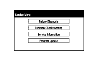
Select "Service Information" on the Service Menu screen.
-
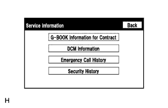
Select "G-BOOK Information for Contract" on the Service Information screen.
-
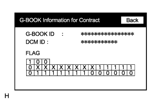
Check the G-BOOK ID or DCM ID.
Tech Tips
The DCM ID is also specified on the telematics transceiver label.
-
-
Replace the display and navigation module display or the telematics transceiver.
-
Replace the display and navigation module display or the telematics transceiver at a dealership.
-
-
Check the ID after replacement.
Tech Tips
-
If the display and navigation module display is replaced, check the G-BOOK ID.
-
If the telematics transceiver is replaced, check the DCM ID.
-
Enter diagnostic mode.
-
Select "Service Information" on the Service Menu screen.
-
Select "G-BOOK Information for Contract" on the Service Information screen.
-
Check the G-BOOK ID or DCM ID.
Tech Tips
The DCM ID is also specified on the telematics transceiver label.
-
-
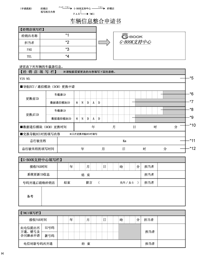
Fill-in the Vehicle Contract Setting Request Form.
-
After filling in the Vehicle Contract Setting Request Form, fax it to the G-BOOK center.
Item Information to Enter Note *1 Enter the dealership name of the applicant. Applicant information *2 Enter the name of the applicant. Applicant information *3 Enter the fax number of the dealership. Applicant information *4 Enter the phone number of the dealership. Applicant information *5 Enter the VIN of the vehicle. Vehicle information *6
-
Enter the G-BOOK ID of the old unit.
-
Left-align the number.
-
If the display and navigation module display is not being replaced, it is not necessary to enter this item.
Used as change-request information from the dealership *7
-
Enter the DCM ID of the old unit.
-
Left-align the number.
-
If the telematics transceiver is not being replaced, it is not necessary to enter this item.
Used as change-request information from the dealership *8
-
Enter the G-BOOK ID of the new unit installed to the vehicle.
-
Left-align the number.
-
If the display and navigation module display is not being replaced, it is not necessary to enter this item.
Used as change-request information from the dealership *9
-
Enter the DCM ID of the new unit installed to the vehicle.
-
Left-align the number.
-
If the telematics transceiver is not being replaced, it is not necessary to enter this item.
Used as change-request information from the dealership *10
-
Enter the date when the telematics transceiver is replaced.
-
If the telematics transceiver is not being replaced, it is not necessary to enter this item.
Used as change-request information from the dealership *11 Enter the mileage on the odometer when the display and navigation module display is replaced. Used as change-request information from the dealership *12 Enter the date that the mileage was recorded. Used as change-request information from the dealership -
-
-
Perform the procedure to resume the G-BOOK service.
Tech Tips
The screen illustrations provided are samples only and may be different from actual screens.
-
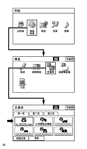
Perform the operations shown in the illustration and select G-BOOK.com.
-
Check that G-BOOK.com is displayed.
-
After the guidance screen is displayed, perform the procedure to resume the G-BOOK service by following the instructions on the screen.
-
-
Perform the procedure to start the emergency call service.
-
After completing the procedure to resume the G-BOOK service, perform the procedure to start the emergency call service by following the instructions on the screen.
Tech Tips
The emergency call service will be available when the procedure is completed successfully.
-
-
-
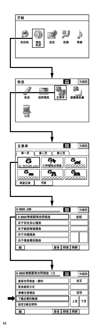
PERFORM "DOWNLOAD NECESSARY DATA" (G-BOOK System)
Tech Tips
If the hard disk drive is replaced on vehicles that have a contract for the G-BOOK service, perform "Download necessary data" after installing the new hard disk drive.
-
Perform the operations shown in the illustration and select "Download necessary data".
Tech Tips
The screen illustrations provided are samples only and may be different from actual screens.
-
-
INITIALIZE PARKING ASSIST MONITOR SYSTEM (Parking Assist Monitor System)
-
When "System initializing" is displayed on the multi-display, correct the steering angle neutral point using the following method.
-
Fully turn the steering wheel to the right and left on the flat ground.
Note
Memorizing the steering angle neutral point must be carried out with the hybrid system started. Apply the parking brake, depress the brake pedal, move the shift lever to P, and ensure that the vehicle is not moving.
Tech Tips
"?" button is displayed at the same time as "System initializing". If the "?" button is selected, this method is displayed.
-
-
-
ADJUST PARKING ASSIST MONITOR SYSTEM (Parking Assist Monitor System)
-
This parking assist monitor system can be set from the diagnostic screen of the multi-display.
-
If the following operations are performed, it is necessary to perform adjustments and checks on the diagnostic screen.
Part Name Operation Adjustment Item Spiral with sensor cable sub-assembly
-
Removal and installation of the spiral with sensor cable sub-assembly
-
Removal and installation of the connector of the spiral with sensor cable sub-assembly
Steering angle neutral point Steering angle setting Spiral with sensor cable sub-assembly Replacement Steering angle neutral point Steering angle setting Parking assist ECU Replacement Parking assist ECU initialization Suspension, tires, etc. The vehicle height changes because of suspension or tire replacement Rear television camera optical axis (Camera position setting) Side television camera optical axis (Camera position setting) Rear television camera assembly
-
Replacement
-
Installation angle of the rear television camera changes because of the removal and installation of the rear television camera, etc.
Rear television camera optical axis (Camera position setting) Display and navigation module display (HDD navigation system) Replacement Vehicle contract setting Tech Tips
-
The adjustment values stored while performing parking assist monitor system calibration are stored in the parking assist ECU.
-
After the power switch is turned off, the display and navigation module display (HDD navigation system) records various types of memory and settings. As a result, after turning the power switch off, make sure to wait for the time specified in the following table before disconnecting the cable from the negative (-) battery terminal.
Waiting Time before Disconnecting Cable from Negative (-) Battery Terminal Specification Waiting Time w/o Telematics transceiver 60 sec. w/ Telematics transceiver 120 sec.
-
-
-
PARKING ASSIST ECU INITIALIZATION (Parking Assist Monitor System)
Tech Tips
Be sure to check for DTCs before performing this procedure.
-
Preparation for adjustment
-
Park the vehicle with the steering wheel centered.
-
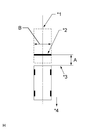
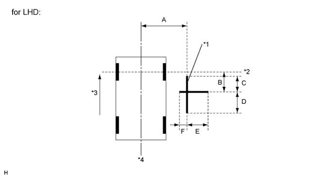
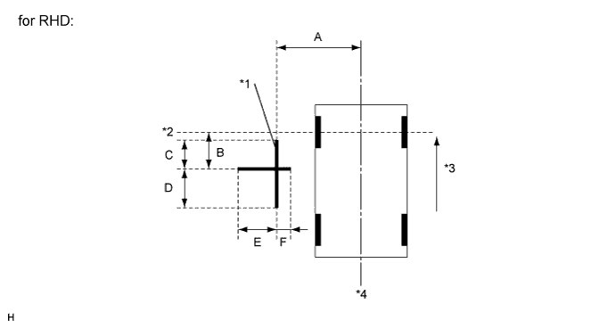
Text in Illustration *1 Vehicle Center *2 Target Bar for Back Camera Adjustment *3 Vehicle End *4 Front Side Set a target bar for optical axis adjustment of the rear television camera.
Tech Tips
Only when adjusting the optical axis of the camera, create a target bar for adjustment.
Tech Tips
-
Set a piece of tape on the ground as the target bar for adjustment. Its width and length are 20 to 30 mm (0.787 to 1.181 in.) and 1995 to 2005 mm (6.545 to 6.578 ft.), respectively. Check the color on the multi-display and choose a tape color which can be easily seen.
-
Before parking the vehicle, be sure to move the vehicle forward and in reverse to check that the tires are facing straight ahead with the steering wheel centered.
-
Check that the back door is fully closed.
-
-
Set a target bar for optical axis adjustment of the side television camera.
Tech Tips
Only when adjusting the optical axis of the camera, create a target bar for adjustment.
Text in Illustration *1 Target Bar for Side Camera Adjustment *2 Front Wheel Axis *3 Front Side *4 Vehicle Center Tech Tips
Target bars for side camera adjustment should be made with 2 pieces of 2.5 cm wide tape; one piece should be 100 cm (3.28 ft.) (C+D) and the other should be 70 cm (2.30 ft.) (E+F) long. Check the tape color on the multi-display and choose a tape color which can be easily seen.
-
-
Start diagnostic mode.
Note
Mode setting must be carried out with the hybrid system started. Apply the parking brake, depress the brake pedal, move the shift lever to P, and ensure that the vehicle is not moving.
Tech Tips
The displayed items may differ depending on vehicle specifications.
-
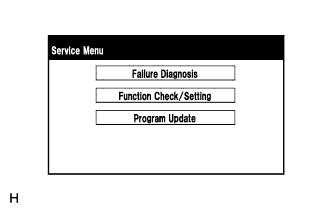
Select "Function Check/Setting" on the Service Menu screen.
-
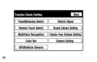
Select "Camera Setting" on the Function Check/Setting screen.
-
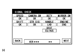
Select "NEXT" on the SIGNAL CHECK screen.
Note
-
When "CHK" (red) is displayed for any items on the SIGNAL CHECK screen, selecting "NEXT" will not change the screen to the SIDE CAMERA POSITION SETTING screen.
-
When "CHK" (red) is displayed for any items on the SIGNAL CHECK screen, perform inspections using the SIGNAL CHECK screen.
Tech Tips
-
When the outer mirrors are retracted, selecting "NEXT" will not change the screen to the SIDE CAMERA POSITION SETTING screen.
-
If the screen does not change to the SIDE CAMERA POSITION SETTING screen even though the outer mirrors are extended, perform the MIRROR SW check on the SIGNAL CHECK screen.
-
If the screen does not change to the SIDE CAMERA POSITION SETTING screen even after "OK" (blue) is displayed as a result of the MIRROR SW check on the SIGNAL CHECK screen, replace the parking assist ECU.
-
-
-
SIDE CAMERA POSITION SETTING
Tech Tips
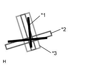
Colors used on the side camera position setting screen
Text in Illustration *1 Target Adjustment Bar for Side Camera Position Setting *2 Red Frame *3 Yellow Frame
-
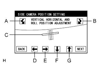
Perform the roll angle adjustment.
-
Select switches A and B to rotate C so that it is parallel to the target adjustment bar.
-
-
Perform the vertical and horizontal position adjustment.
-
Select the directional switches D, E, F and G to move C so that the target adjustment bar is centered in C.
-
-
Select "NEXT" to display SIDE VERIFY MODE.
-
-
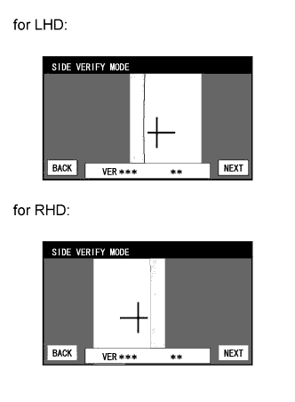
SIDE VERIFY MODE
-
Check that the red cross and the target adjustment bar are aligned.
Tech Tips
If they are not aligned, select "BACK" and perform SIDE CAMERA POSITION SETTING again.
-
Select "NEXT" to store the side camera aiming adjustment value and change the screen to the STEERING ANGLE SETTING screen.
Tech Tips
-
When "NEXT" is selected, a beep will sound to confirm that the side camera aiming adjustment values have been stored.
-
The adjustment value will not be stored unless "NEXT" is selected.
-
-
-
STEERING ANGLE SETTING
-
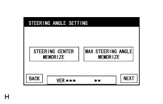
Perform the STEERING CENTER MEMORIZE operation.
-
Check that the steering wheel is centered, and then select "STEERING CENTER MEMORIZE".
Tech Tips
When performing removal and installation, or replacement of the television camera, steering angle adjustment is not required.
-
-
Perform the MAX STEERING ANGLE MEMORIZE operation.
-
After adjusting the steering angle neutral point, turn the steering wheel to the left and right lock positions and select "MAX STEERING ANGLE MEMORIZE". The maximum steering angle is then stored and the screen changes to the BACK CAMERA POSITION SETTING screen.
Tech Tips
The "NEXT" button does not respond until the system stores the steering angle neutral point and maximum steering angle.
Tech Tips
-
It is also possible to start by initially turning the steering to the right side.
-
When "MAX STEERING ANGLE MEMORIZE" is selected, a beep will sound to confirm that the steering adjustment values have been stored.
-
The adjustment value will not be stored unless "MAX STEERING ANGLE MEMORIZE" is selected after turning the steering wheel side to side.
-
When "BACK" is selected, the screen changes to SIDE VERIFY MODE without storing the set values.
-
Even if no DTCs are detected, selecting "MAX STEERING ANGLE MEMORIZE" may not cause the adjustment value to be stored if the steering sensor is malfunctioning.
-
If selecting "MAX STEERING ANGLE MEMORIZE" does not cause the adjustment value to be stored after adjusting the steering angle, replace the spiral with sensor cable sub-assembly.
-
-
-
-
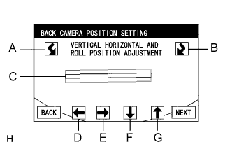
BACK CAMERA POSITION SETTING
Tech Tips
-
When the back door is open, the "Back door is open. Do not use the rear view monitor when the back door is not completely closed." message will be displayed and camera position setting will not be possible.
-
If the "Back door is open. Do not use the rear view monitor when the back door is not completely closed." message is displayed even when the back door is closed, perform inspections according to Problem Symptoms Table (A back door open warning message is displayed even after back door is closed).
-
Perform the roll angle adjustment.
-
Select switches A and B to rotate C so that it is parallel to the target adjustment bar.
-
-
Perform the vertical and horizontal position adjustment.
-
Select the directional switches D, E, F and G to move C so that the target adjustment bar is centered in C.
-
-
Select the "NEXT" button on the BACK CAMERA POSITION SETTING screen.
-
-
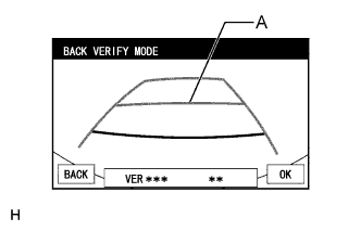
BACK VERIFY MODE
-
Check that A and the target adjustment bar are overlapping.
-
If the steering angle neutral point is not aligned, perform the STEERING CENTER MEMORIZE and MAX STEERING ANGLE MEMORIZE operations.
-
If A and the target adjustment bar are not aligned even if the tires are aligned straight ahead, perform the camera position setting operation.
-
-
Selecting "OK" will return the screen to the Service Menu screen, and complete the adjustment.
Tech Tips
-
The update is not completed until "OK" is selected.
-
When "OK" is selected, a beep will sound to confirm that the rear camera aiming adjustment values have been stored.
-
-
-
Finish diagnostic mode.
-
-
BACK CAMERA POSITION SETTING (Parking Assist Monitor System)
Tech Tips
Be sure to check for DTCs before performing this procedure.
-
Preparation for adjustment
-
Park the vehicle with the steering wheel centered.
-
Text in Illustration *1 Vehicle Center *2 Target Bar for Back Camera Adjustment *3 Vehicle End *4 Front Side Set a target bar for optical axis adjustment of the rear television camera.
Tech Tips
Only when adjusting the optical axis of the camera, create a target bar for adjustment.
Tech Tips
-
Set a piece of tape on the ground as the target bar for adjustment. Its width and length should be 20 to 30 mm (0.787 to 1.181 in.) and 1995 to 2005 mm (6.545 to 6.578 ft.), respectively. Check the color on the multi-display and choose a tape color which can be easily seen.
-
Before parking the vehicle, be sure to move the vehicle forward and in reverse to check that the tires are facing straight ahead with the steering wheel centered.
-
Check that the back door is fully closed.
-
-
-
Start diagnostic mode.
Note
Mode setting must be carried out with the hybrid system started. Apply the parking brake, depress the brake pedal, move the shift lever to P, and ensure that the vehicle is not moving.
Tech Tips
The displayed items may differ depending on vehicle specifications.
-
Select "Function Check/Setting" on the "Service Menu" screen.
-
Select "Camera Setting" on the Function Check/Setting screen.
-
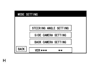
Select "BACK CAMERA SETTING" on the MODE SETTING screen.
Tech Tips
To select a grayed out item, select and hold the item for 2 seconds or more.
-
Select "NEXT" on the SIGNAL CHECK screen.
Note
-
When "CHK" (red) is displayed for any items on the SIGNAL CHECK screen, selecting "NEXT" will not change the screen to the BACK CAMERA POSITION SETTING screen.
-
When "CHK" (red) is displayed for any items on the SIGNAL CHECK screen, perform inspections using the SIGNAL CHECK screen.
-
-
-
BACK CAMERA POSITION SETTING
Tech Tips
-
When the back door is open, the "Back door is open. Do not use the rear view monitor when the back door is not completely closed." message will be displayed and camera position setting will not be possible.
-
If the "Back door is open. Do not use the rear view monitor when the back door is not completely closed." message is displayed even when the back door is closed, perform inspections according to Problem Symptoms Table (A back door open warning message is displayed even after back door is closed).
-
Perform the roll angle adjustment.
-
Select switches A and B to rotate C so that it is parallel to the target adjustment bar.
-
-
Perform the vertical and horizontal position adjustment.
-
Select the directional switches D, E, F and G to move C so that the target adjustment bar is centered in C.
-
-
Select the "NEXT" button on the "BACK CAMERA POSITION SETTING" screen.
-
-
BACK VERIFY MODE
-
Check that A and the target adjustment bar are overlapping.
-
If the steering angle neutral point is not aligned, perform the STEERING CENTER MEMORIZE and MAX STEERING ANGLE MEMORIZE operations.
-
If A and the target adjustment bar are not aligned even if the tires are aligned straight ahead, perform the camera position setting operation.
-
-
Selecting "OK" will return the screen to the Service Menu, and complete the adjustment.
Tech Tips
-
The update is not completed until "OK" is selected.
-
When "OK" is selected, a beep will sound to confirm that the rear camera aiming adjustment values have been stored.
-
-
-
Finish diagnostic mode.
-
-
INITIALIZE SIDE MONITOR SYSTEM (Side Monitor System)
-
When "System initializing" is displayed on the multi-display, correct the steering angle neutral point using the following method.
-
Fully turn the steering wheel to the right and left on the flat ground.
Note
Memorizing the steering angle neutral point must be carried out with the hybrid system started. Apply the parking brake, depress the brake pedal, move the shift lever to P, and ensure that the vehicle is not moving.
Tech Tips
"?" button is displayed at the same time as "System initializing". If the "?" button is selected, this method is displayed.
-
-
-
ADJUST SIDE MONITOR SYSTEM (Side Monitor System)
-
This side monitor system can be set from the diagnostic screen of the multi-display.
-
If the following operations are performed, it is necessary to perform adjustments and checks on the diagnostic screen.
Part Name Operation Adjustment Item Spiral with sensor cable sub-assembly
-
Removal and installation of the spiral with sensor cable sub-assembly
-
Removal and installation of the connector of the spiral with sensor cable sub-assembly
Steering angle neutral point Steering angle setting Spiral with sensor cable sub-assembly Replacement Steering angle neutral point Steering angle setting Parking assist ECU Replacement Parking assist ECU initialization Suspension, tires, etc. The vehicle height changes because of suspension or tire replacement Rear television camera optical axis (Camera position setting) Side television camera optical axis (Camera position setting) Side television camera assembly
-
Replace
-
Installation angle of the side television camera changes because of the removal and installation of the side television camera, etc.
Side television camera optical axis (Camera position setting) Outer rear view mirror assembly (passenger side) Replacement Side television camera optical axis (Camera position setting) Display and navigation module display (HDD navigation system) Replacement Vehicle contract setting Tech Tips
-
The adjustment values stored while performing side monitor system calibration are stored in the parking assist ECU.
-
After the power switch is turned off, the display and navigation module display (HDD navigation system) records various types of memory and settings. As a result, after turning the power switch off, make sure to wait for the time specified in the following table before disconnecting the cable from the negative (-) battery terminal.
Waiting Time before Disconnecting Cable from Negative (-) Battery Terminal Specification Waiting Time w/o Telematics transceiver 60 sec. w/ Telematics transceiver 120 sec.
-
-
-
SIDE CAMERA POSITION SETTING (Side Monitor System)
Tech Tips
Be sure to check for DTCs before performing this procedure.
-
Preparation for adjustment
-
Park the vehicle with the steering wheel centered.
-
Set a target bar for optical axis adjustment of the side television camera.
Tech Tips
Only when adjusting the optical axis of the camera, create a target bar for adjustment.
Text in Illustration *1 Target Bar for Side Camera Adjustment *2 Front Wheel Axis *3 Front Side *4 Vehicle Center Tech Tips
Target bars for side camera adjustment should be made with 2 pieces of 2.5 cm wide tape; one piece should be 100 cm (3.28 ft.) (C+D) and the other should be 70 cm (2.30 ft.) (E+F) long. Check the tape color on the multi-display and choose a tape color which can be easily seen.
-
-
Start the diagnostic mode.
Note
Mode setting must be carried out with the hybrid system start. Apply the parking brake, depress the brake pedal, move the shift lever to P, and ensure that the vehicle is not moving.
-
Select "Function Check/Setting" on the Service Menu screen.
-
Select the "Camera Setting" on the Function Check/Setting screen."
-
Select the "SIDE CAMERA SETTING" on the MODE SETTING screen.
-
Select "NEXT" on the SIGNAL CHECK screen.
Note
-
When "CHK" (red) is displayed for any items on the SIGNAL CHECK screen, selecting "NEXT" will not change the screen to the SIDE CAMERA POSITION SETTING screen.
-
When "CHK" (red) is displayed for any items on the SIGNAL CHECK screen, perform inspections using the SIGNAL CHECK screen.
Tech Tips
-
When the outer mirrors are retracted, selecting "NEXT" will not change the screen to the SIDE CAMERA POSITION SETTING screen.
-
If the screen does not change to the SIDE CAMERA POSITION SETTING screen even though the outer mirrors are extended, perform the MIRROR SW check on the SIGNAL CHECK screen.
-
If the screen does not change to the SIDE CAMERA POSITION SETTING screen even after "OK" (blue) is displayed as a result of the MIRROR SW check on the SIGNAL CHECK screen, replace the parking assist ECU.
-
-
-
SIDE CAMERA POSITION SETTING
Tech Tips
Colors used on the side camera position setting screen
Text in Illustration *1 Target Bar for Side Camera Adjustment *2 Red Frame *3 Yellow Frame
-
Perform the roll angle adjustment.
-
Select switches A and B to rotate C so that it is parallel to the target adjustment bar.
-
-
Perform the vertical and horizontal position adjustment.
-
Select the directional switches D, E, F and G to move C so that the target adjustment bar is centered in C.
-
-
Select "NEXT" to display SIDE VERIFY MODE.
-
-
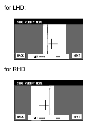
SIDE VERIFY MODE
-
Check that the red cross and the target adjustment bar are aligned.
Tech Tips
If they are not aligned, select "BACK" and perform SIDE CAMERA POSITION SETTING again.
-
Select "OK" to store the side camera aiming adjustment value and change the screen to the STEERING ANGLE SETTING screen.
Tech Tips
-
When "OK" is selected, a beep will sound to confirm that the side camera aiming adjustment values have been stored.
-
The adjustment value will not be stored unless "OK" is selected.
-
-
-
Finish the diagnostic mode.
-
-
INITIALIZE ROOF SUNSHADE ECU (SLIDING ROOF DRIVE GEAR SUB-ASSEMBLY) (Roof Sunshade System)
Note
-
When the roof sunshade, roof sunshade ECU (sliding roof drive gear sub-assembly) or sliding roof housing is replaced or removed and installed, the roof sunshade ECU (sliding roof drive gear sub-assembly) requires initialization (pulse sensor initial position setting), as the roof sunshade position cannot be determined. If initialization is not performed, the auto slide open and close function may not operate, or the roof sunshade may move in reverse or become misaligned.
-
During initialization, do not apply a physical shock, such as opening/closing a door or driving the vehicle at 5 km/h (3 mph) or more, to the vehicle.
-
Check the operation of the roof sunshade.
Roof Sunshade Operation Proceed to Auto operation does not operate. Procedure A Auto operation operates normally, but the roof sunshade does not stop at the correct fully closed position. Procedure B Auto operation operates normally, but the roof sunshade erroneously reverses operation while sliding closed. Procedure C Tech Tips
Before performing initialization, make sure that there is no foreign matter on the guide rails and the guide rails are not deformed.
-
Procedure A (Normal initialization)
-
Turn the power switch on (IG).
-
Press and hold the CLOSE switch.
-
The roof sunshade starts sliding close operation and stops at the fully closed position.
-
After the roof sunshade stops, continue pressing the CLOSE switch for 1 second or more.
-
Check that the roof sunshade moves slightly rearward and stops at the correct fully closed position.
Tech Tips
The initialization process ends when this operation completes.
-
-
Procedure B (Resetting the memorized position)
-
Turn the power switch on (IG).
-
Press and hold the CLOSE switch until the roof sunshade stops and then release the switch.
-
Press and hold the CLOSE switch again for 10 seconds or more.
-
The roof sunshade starts sliding closed operation and stops at the fully closed position.
-
After the roof sunshade stops, continue pressing the CLOSE switch for 1second or more.
-
Check that the roof sunshade moves slightly rearward and stops at the correct fully closed position.
Tech Tips
The initialization process ends when this operation completes.
-
-
Procedure C (Clear initialization)
-
Turn the power switch on (IG).
-
Press and hold the CLOSE switch until the following movements finish and then release the switch: starts sliding closed → erroneously reverses → stops operation for 10 seconds → starts sliding closed → stops at the fully closed position.
-
Perform Procedure A.
-
-
-
INITIALIZE POWER WINDOW CONTROL SYSTEM (POWER WINDOW REGULATOR MOTOR ASSEMBLY (ALL DOORS)) (Power Window Control System)
CAUTION:
When the power window regulator motor assembly is reinstalled or replaced, the power window control system must be initialized. Functions such as the auto up and down, jam protection, remote control and key-off operation do not operate if the initialization is not performed.
Tech Tips
When the battery is replaced, it is not necessary to initialize the power window regulator motor assembly.
Note
-
When the power window regulator motor assembly is replaced, DTC B2313 is output. Clear the DTC after the initialization.
-
When performing initialization, do not perform any other procedures.
-
When performing initialization, use the power window switch of each door to initialize each door window.
-
After a door glass or a door glass run has been replaced, the jam protection function may operate unexpectedly when the auto up function is used, due to detection of a value different from the operation learned value of the door glass movement speed. In such cases, the auto up function can be reinitialized by repeating the following operation at least 5 times:
-
Open the power window by fully pushing down the multiplex network master switch assembly or power window regulator switch assembly.
-
Close the power window by fully pulling up the multiplex network master switch assembly or power window regulator switch assembly and holding it at the auto up position.
-
If the initialization is not completed properly, the LIN communication system may have a malfunction.
-
Initialization procedure when replacing the power window regulator motor assembly with a new one:
-
Connect the battery and turn the power switch on (IG) (at this time, the LED on the multiplex network master switch assembly or power window regulator switch assembly blinks to indicate that it is ready for initialization).
-
Fully open the window by fully pushing down the multiplex network master switch assembly or power window regulator switch assembly, and hold the switch for 1 second or more after the window is fully opened.
-
Fully close the power window by fully pulling up the multiplex network master switch assembly or power window regulator switch assembly, and hold the switch for 1 second or more after the window is fully closed to reset the glass position. The LED on the multiplex network master switch assembly or power window regulator switch assembly stops blinking and illuminates to indicate that the initialization is complete.
-
-
Initialization procedure when removing/installing the power window regulator motor assembly:
-
Connect the battery and turn the power switch on (IG).
-
Fully close the power window by fully pulling up the multiplex network master switch assembly or power window regulator switch assembly, and hold the switch for 6 seconds or more after the window is fully closed (if the power window does not move or stops halfway even when the switch is fully pulled, release the switch and fully pull it again).
-
Fully open the window by pushing down the multiplex network master switch assembly or power window regulator switch assembly, and hold the switch for 1 second or more after the window is fully opened.
-
Release the multiplex network master switch assembly or power window regulator switch assembly. Then fully push down and hold the switch for 4 seconds or more.
-
Fully close the power window by fully pulling up the multiplex network master switch assembly or power window regulator switch assembly, and hold the switch for 1 second or more after the window is fully closed to reset the glass position and complete the initialization.
-
-
Initialization procedure when the power window does not fully open:
-
Connect the battery and turn the power switch on (IG).
-
Fully close the power window by fully pulling up the multiplex network master switch assembly or power window regulator switch assembly, and hold the switch for 6 seconds or more after the window is fully closed (if the power window does not move or stops halfway even when the switch is fully pulled, release the switch and fully pull it again).
-
Fully open the window by pushing down the multiplex network master switch assembly or power window regulator switch assembly, and hold the switch for 1 second or more after the window is fully opened.
-
Release the multiplex network master switch assembly or power window regulator switch assembly. Then fully push down and hold the switch for 4 seconds or more.
-
Fully close the power window by fully pulling up the multiplex network master switch assembly or power window regulator switch assembly, and hold the switch for 1 second or more after the window is fully closed to reset the glass position and complete the initialization.
-
-
-
INITIALIZE SLIDING ROOF ECU (SLIDING ROOF DRIVE GEAR SUB-ASSEMBLY) (Sliding Roof System)
Note
-
When the sliding roof glass, sliding roof ECU (sliding roof drive gear sub-assembly) or sliding roof housing is replaced or removed and installed, the sliding roof drive gear requires initialization (pulse sensor initial position setting), as the glass position cannot be determined. If initialization is not performed, the auto slide open and close / tilt up and down function may not operate, or the sliding roof may move in reverse or become misaligned.
-
During initialization, do not apply a physical shock, such as opening/closing a door or driving the vehicle at 5 km/h (3 mph) or more, to the vehicle and do not perform the following electrical operations:
-
Cranking the engine
-
Turning the power switch from on (IG) to off
-
Operating the power window switches
-
Operating the window defogger switch
-
Operating the blower switch
-
Locking/Unlocking a door
-
Operating the headlight dimmer switch
-
Operating the power seat switch
Tech Tips
When the cable of the negative (-) auxiliary battery terminal or the drive gear connector is disconnected and reconnected, sliding roof drive gear (pulse sensor initial position setting) initialization is not necessary.
-
Perform initialization according to the table below.
Condition of Sliding Roof Proceed to Auto slide open and close / tilt up and down function does not operate Procedure A Sliding roof moves in reverse direction during tilt down operation Procedure B Sliding roof moves in reverse direction during slide close operation Procedure C Tech Tips
Before performing initialization, make sure that there is no foreign matter on the guide rails and the guide rails are not deformed.
-
Procedure A
-
Turn the power switch on (IG).
-
Close the sliding roof to the fully closed position.
-
Press and hold the TILT UP or SLIDE CLOSE switch to perform the following operations: tilt up → approximately 1 second pause → tilt down → slide open → slide close.
Note
Make sure not to release the switch during the initialization. If the switch is released, perform the initialization again.
-
The initialization is completed.
-
-
Procedure B
-
Turn the power switch on (IG).
-
Press the TILT UP switch until the sliding roof stops.
Tech Tips
If the glass becomes misaligned or does not fully tilt up, perform the following operations:
-
Operate the SLIDE CLOSE switch until the sliding roof stops moving.
-
Operate the TILT UP switch until the sliding roof stops moving, then proceed to the next step.
-
-
Release the switch.
-
Press the TILT UP switch for 10 seconds or more to perform the following operations: tilt up → approximately 1 second pause → tilt down → slide open → slide close.
Note
Make sure not to release the switch during the initialization. If the switch is released, perform the initialization again.
-
The initialization is completed.
-
-
Procedure C
-
Turn the power switch on (IG).
-
Press and hold the SLIDE CLOSE switch to perform the following operations: slide close → move in reverse direction → 10 second pause → slide close.
Note
Make sure not to release the switch during the initialization. If the switch is released, perform the initialization again.
-
After the sliding roof stops in the fully closed position, release the switch.
-
Perform procedure A.
-
-
-
-
INITIALIZATION (Lighting System (EXT))
Note
-
Initialize the AFS ECU (headlight swivel ECU assembly) when the AFS ECU (headlight swivel ECU assembly) is replaced.
-
If the vehicle is not equipped with air suspension system, initialize the AFS ECU (headlight swivel ECU assembly) (set the zero point of the height control sensor in the AFS ECU (headlight swivel ECU assembly)) after the vehicle height changes due to replacement of suspension components or after performing such operations as removal and reinstallation or replacement of the rear height control sensor sub-assembly RH.
-
If the vehicle is not equipped with air suspension system, adjust the headlight aim after initializing the AFS ECU (headlight swivel ECU assembly).
-
When a malfunction is detected in the automatic headlight beam level control system or AFS, height control sensor signal initialization is impossible. Perform troubleshooting before initialization.
-
CHECK VEHICLE CONDITION
-
Check the vehicle condition.
Result Result Proceed to w/o Air Suspension System A w/ Air Suspension System B
B
Go to step 7
A
-
-
CHECK VEHICLE CONDITION
-
Check the vehicle condition.
Result Result Proceed to The AFS ECU (headlight swivel ECU assembly) has been replaced with a new one. A Removal and reinstallation of the AFS ECU (headlight swivel ECU assembly), replacement of the rear height control sensor sub-assembly RH, removal and reinstallation of the rear height control sensor sub-assembly RH, replacement of the suspension, etc. have been performed. B
B
Go to step 4
A
-
-
SYNCHRONIZE VEHICLE INFORMATION
-
When using the intelligent tester:
-
Turn the power switch off.
-
Connect the intelligent tester to the DLC3.
-
Turn the power switch on (IG), and check that the AFS OFF indicator light continuously blinks at 0.5 Hz.
-
Enter the following menus: Main Body / AFS / Utility / ECU Information Sync / Next.
-
Check what is displayed on the screen of the intelligent tester and press "Next".
-
Check that the AFS OFF indicator light continuously blinks 6 times at 2 Hz.
-
Press "Exit" and turn the power switch off.
-
-
When not using the intelligent tester:
-
Turn the power switch on (IG), and check that the AFS OFF indicator light continuously blinks at 0.5 Hz.
-
Turn the low beam headlights on and off 8 times using the light control switch within 20 seconds after turning the power switch on (IG).
Tech Tips
If the light control switch operation cannot be finished within 20 seconds, turn the power switch off. Then, turn the power switch on (IG) and restart again.
Note
Turn the low beam headlights on and off at less than 2-second intervals.
-
Check that the AFS OFF indicator light continuously blinks 6 times at 2 Hz.
-
Turn the power switch off.
NEXT
-
-
-
PREPARE VEHICLE FOR INITIALIZATION
-
Unload the trunk and vehicle, ensuring that the spare tire, tools and jack are in their original positions.
-
Check that there are no occupants in the vehicle.
-
Turn off the headlights.
-
Stop the vehicle on a level surface and keep the vehicle height unchanged.
NEXT
-
-
CHECK AFS OFF INDICATOR LIGHT
-
Turn the power switch on (IG), and check the indicator light.
OK Condition Specified Condition The AFS ECU (headlight swivel ECU assembly) has been replaced with a new one. Indicator light continuously blinks 6 times at 2 Hz. Removal and reinstallation of the AFS ECU (headlight swivel ECU assembly), replacement of the rear height control sensor sub-assembly RH, removal and reinstallation of the rear height control sensor sub-assembly RH, replacement of the suspension, etc. have been performed. Indicator light comes on for approximately 3 seconds, and then goes off (bulb check function). Tech Tips
If the indicator light does not come on when turning the power switch on (IG), inspect and repair it according to Problem Symptoms Table.
NG
GO TO PROBLEM SYMPTOMS TABLE
OK
-
-
INITIALIZATION
-
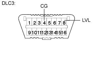
Connect terminals 4 (CG) and 8 (LVL) of the DLC3 using SST.
- SST
- 09843-18040
-
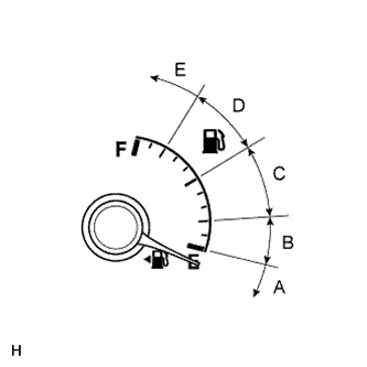
Turn the low beam headlights on and off using the light control switch within 20 seconds after connecting the terminals.
Tech Tips
The number of times the low beam headlights need to be turned on and off is determined by the present fuel level as shown below.
Fuel Level Number of Times to Turn Low Beam Headlights on and off Fuel level is within A range. 1 Fuel level is within B range. 2 Fuel level is within C range. 3 Fuel level is within D range. 4 Fuel level is within E range. 5 Note
-
Turn the low beam headlights on and off at less than 3-second intervals.
-
Be sure to operate the light control switch from outside the vehicle.
-
-
Check the indicator light.
OK Condition Specified Condition The AFS ECU (headlight swivel ECU assembly) has been replaced with a new one. Blinks 6 times at 2 Hz → Continuously blinks N*1 times at 2 Hz. Removal and reinstallation of the AFS ECU (headlight swivel ECU assembly), replacement of the rear height control sensor sub-assembly RH, removal and reinstallation of the rear height control sensor sub-assembly RH, replacement of the suspension, etc. have been performed. Off → Continuously blinks N*1 times at 2 Hz. Tech Tips
-
*1: The number of times that the indicator blinks is determined by the number of times the low beam headlights are turned on and off.
-
If initialization cannot be finished normally, disconnect SST from the DLC3 and turn the power switch off. Then, restart from procedure 1.
NG
GO TO PROBLEM SYMPTOMS TABLE
OK
TURN POWER SWITCH OFF (END) -
-
-
SYNCHRONIZE VEHICLE INFORMATION
Tech Tips
If the AFS ECU (headlight swivel ECU assembly) is replaced with a new one, synchronize the vehicle information.
-
When using the intelligent tester:
-
Turn the power switch off.
-
Connect the intelligent tester to the DLC3.
-
Turn the power switch on (IG), and check that the AFS OFF indicator light continuously blinks at 0.5 Hz.
-
Enter the following menus: Main Body / AFS / Utility / ECU Information Sync / Next.
-
Check what is displayed on the screen of the intelligent tester and press "Next".
-
Press "Exit" and turn the power switch off.
-
-
When not using the intelligent tester:
-
Turn the power switch on (IG), and check that the AFS OFF indicator light continuously blinks at 0.5 Hz.
-
Turn the low beam headlights on and off 8 times using the light control switch within 20 seconds after turning the power switch on (IG).
Tech Tips
If the light control switch operation cannot be finished within 20 seconds, turn the power switch off. Then, turn the power switch on (IG) and restart again.
Note
Turn the low beam headlights on and off at less than 2-second intervals.
-
Turn the power switch off.
NEXT
END -
-
-