STEERING GEAR INSTALLATION

-
INSTALL TIE ROD ASSEMBLY LH
-
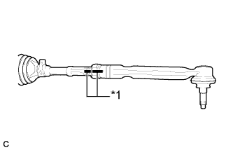
Text in Illustration *1 Matchmark Install the lock nut and tie rod assembly LH to the steering rack end sub-assembly until the matchmarks are aligned.
Tech Tips
After adjusting toe-in, tighten the lock nut.
-
-
INSTALL TIE ROD ASSEMBLY RH
Tech Tips
Perform the same procedure as for the LH side.
-
INSTALL STEERING LINK ASSEMBLY
-
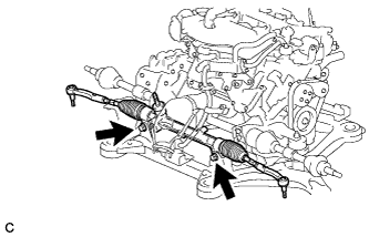
Install the steering link assembly with the 2 bolts and 2 nuts.
- Torque:
- 70 N*m { 713 kgf*cm, 51 ft.*lbf }
Note
-
Make sure to tighten the bolts starting from the steering link assembly pinion shaft side.
-
Because the nut has its own stopper, do not turn the nut. Tighten the bolt with the nut secured.
-
-
INSTALL FRONT STABILIZER BAR (w/o Active Stabilizer System)
-
Install the front stabilizer bar to the front frame assembly.
-
-
INSTALL FRONT ACTIVE STABILIZER CONTROL ACTUATOR ASSEMBLY (w/ Active Stabilizer System)
-
Install the front active stabilizer control actuator assembly to the front frame assembly.
Note
-
Take care not to damage the front active stabilizer control actuator assembly wire harness.
-
Avoid any impact to the front active stabilizer control actuator assembly.
-
Do not drop the front active stabilizer control actuator assembly. If it is dropped, replace it with a new one.
-
-
-
INSTALL FRONT NO. 1 STABILIZER BRACKET LH
-
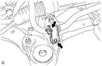
Install the front No. 1 stabilizer bracket LH to the front frame assembly with the 2 bolts.
- Torque:
- 29 N*m { 296 kgf*cm, 21 ft.*lbf }
-
-
INSTALL FRONT NO. 1 STABILIZER BRACKET RH
Tech Tips
Perform the same procedure as for the LH side.
-
INSTALL ENGINE ASSEMBLY WITH TRANSAXLE
Tech Tips
Refer to the procedure from Install Engine Assembly with Transaxle Click here.
-
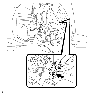
CONNECT TIE ROD ASSEMBLY LH
-
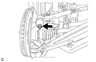
Connect the tie rod assembly LH to the steering knuckle with the nut.
- Torque:
- 49 N*m { 500 kgf*cm, 36 ft.*lbf }
-
Install a new cotter pin.
Note
Further tighten the nut up to 60° if the holes for the cotter pin are not aligned.
-
-
CONNECT TIE ROD ASSEMBLY RH
Tech Tips
Perform the same procedure as for the LH side.
-
CONNECT STEERING INTERMEDIATE SHAFT ASSEMBLY
-
Align the matchmarks on the steering intermediate shaft assembly and steering link assembly.
-
Install the bolt.
- Torque:
- 35 N*m { 360 kgf*cm, 26 ft.*lbf }
-
-
INSTALL FRONT WHEELS
- Torque:
- 103 N*m { 1050 kgf*cm, 76 ft.*lbf }
-
INSPECT AND ADJUST FRONT WHEEL ALIGNMENT
Tech Tips
-
INSPECT STEERING WHEEL CENTER POINT