STEERING WHEEL INSPECTION

-
INSPECT STEERING PAD SWITCH ASSEMBLY
-
Measure the resistance according to the value(s) in the table below.
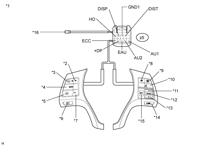
Standard Resistance Tester Connection Switch Condition Specified Condition z5-1 (HO) - Terminal A Always Below 2.5 Ω z5-2 (DISP) - z5-3 (GND1) No switch pushed 95 to 105 Ω z5-2 (DISP) - z5-3 (GND1) Menu switch: pushed Below 2.5 Ω z5-2 (DISP) - z5-3 (GND1) ENTER switch: pushed 312 to 345 Ω z5-2 (DISP) - z5-3 (GND1) Down switch: pushed 950 to 1050 Ω z5-2 (DISP) - z5-3 (GND1) Up switch: pushed 2955 to 3265 Ω z5-4 (DIST) - z5-10 (ECC) Distance control switch: ON Below 2.5 Ω z5-4 (DIST) - z5-10 (ECC) No switch pushed 10 kΩ or higher z5-7 (+DP) - z5-8 (EAU) Side monitor main switch: pushed Below 2.5 Ω z5-7 (+DP) - z5-8 (EAU) No switch pushed 10 kΩ or higher z5-9 (AU2) - z5-8 (EAU) No switch pushed 95 to 105 kΩ z5-9 (AU2) - z5-8 (EAU) MODE switch: pushed Below 2.5 Ω z5-9 (AU2) - z5-8 (EAU) Voice switch: pushed 2954 to 3265 Ω z5-9 (AU2) - z5-8 (EAU) On Hook switch: pushed 312 to 345 Ω z5-9 (AU2) - z5-8 (EAU) Off Hook switch: pushed 950 to 1050 Ω z5-10 (AU1) - z5-8 (EAU) No switch pushed 95 to 105 kΩ z5-10 (AU1) - z5-8 (EAU) Seek+ switch: pushed Below 2.5 Ω z5-10 (AU1) - z5-8 (EAU) Seek- switch: pushed 312 to 345 Ω z5-10 (AU1) - z5-8 (EAU) Volume+ switch: pushed 950 to 1050 Ω z5-10 (AU1) - z5-8 (EAU) Volume- switch: pushed 2954 to 3265 Ω Tech Tips
If the result is not as specified, replace the steering pad switch assembly.
Text in Illustration *1 Component without harness connected
(Steering Pad Switch Assembly)
*2 Volume+ *3 Volume- *4 MODE *5 Seek- *6 Side Monitor Main Switch *7 Seek+ *8 Off Hook *9 On Hook *10 Voice Switch *11 UP Switch *12 ENTER Switch *13 DOWN Switch *14 Distance Control Switch *15 MENU Switch *16 Terminal A -
Check the illumination.
-
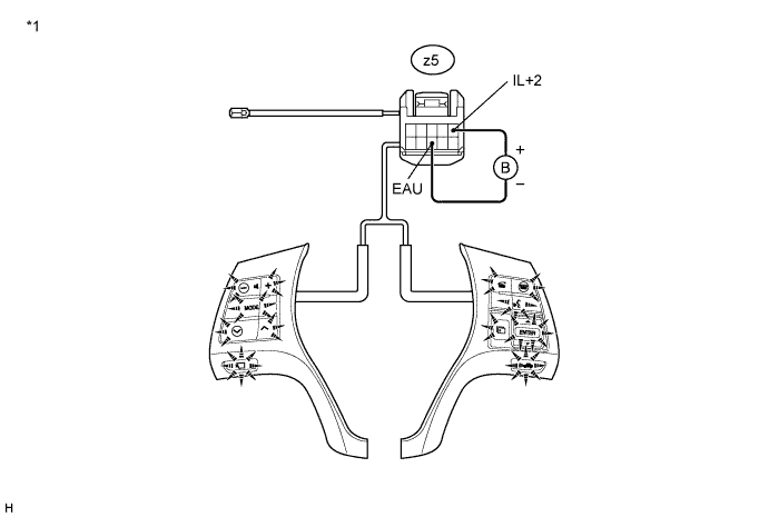
Connect a positive (+) lead to terminal IL+2 and a negative (-) lead to terminal EAU of the steering pad switch assembly connector.
-
Check that the switch illumination comes on.
OK Steering pad switch illumination comes on. Tech Tips
If the result is not as specified, replace the steering pad switch assembly.
Text in Illustration *1 Component without harness connected
(Steering Pad Switch Assembly)
-
-