STEERING LOCK SYSTEM Unable to Lock Steering Wheel
DESCRIPTION
The steering lock ECU (steering lock actuator assembly) sends an unlock position signal to the power management control ECU. On receiving the signal, the power management control ECU permits an engine start. This prevents the engine from being started with the steering locked.
The steering lock actuator activates the steering lock motor and moves the lock bar into the steering column to lock the steering wheel.
When the steering lock is operating, the steering lock may not lock when the lock bar is not aligned with the lock hole of the steering column. In this case, the steering lock can be locked by turning the steering wheel a little in the same manner as is done for a vehicle with a mechanical key to change the position of the lock hole.
The diagnosis information of the steering lock ECU (steering lock actuator assembly) is transmitted to the intelligent tester via the certification ECU (smart key ECU assembly) as the steering lock ECU (steering lock actuator assembly) is not connected to the CAN communication system.
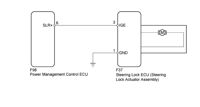
WIRING DIAGRAM
INSPECTION PROCEDURE
Note
-
If the steering lock ECU (steering lock actuator assembly) is replaced, with the power switch off and the shift lever to P, open and close the driver side door to record the current lock position into the steering lock ECU (steering lock actuator assembly). If this is not performed, the engine may not start.
-
After replacing the steering lock ECU (steering lock actuator assembly), ID code box (immobiliser Code ECU) or certification ECU (smart key ECU assembly), registration must be performed refer to the Service Bulletin for the registration method.
Tech Tips
When the power switch is off, the main body ECU may occasionally go into a non-active state called sleep mode. Therefore, before proceeding with the inspection, it is necessary to perform the following steps to wake up the ECU:
With the power switch off, open the driver door. Then (with the power switch still off) open and close any door several times at 1.5 second intervals.
PROCEDURE
-
READ VALUE USING INTELLIGENT TESTER (LOCK/UNLOCK RECEIVE)
-
Use the Data List to check if the steering lock command is functioning properly.
Entry & Start Tester Display Measurement Item/Range Normal Condition Diagnostic Note Lock/Unlock Receive Steering lock command reception record/
Yes or No
Yes: Steering lock/unlock signal received
No: Steering lock/unlock signal not received
- OK The certification ECU (smart key ECU assembly) receives an unlock request signal within 10 seconds of starting the engine, and "Yes" is displayed on the intelligent tester screen.
NG 
READ VALUE USING INTELLIGENT TESTER (DRIVER SIDE DOOR COURTESY SWITCH) Click here
OK 
-
-
INSPECT STEERING LOCK ECU (STEERING LOCK ACTUATOR ASSEMBLY)
-
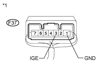
Text in Illustration *1 Component with harness connected
(Steering Lock ECU)
Move the shift lever to P.
-
Measure the voltage according to the value(s) in the table below.
Standard Voltage Tester Connection Condition Specified Condition F37-3 (IGE) - F37-1 (GND) Steering lock motor operating immediately after turning the power switch from off to on (IG) Below 1 V F37-3 (IGE) - F37-1 (GND) Steering lock motor not operating 11 to 14 V
NG 
REPAIR OR REPLACE HARNESS OR CONNECTOR
OK
-
-
CHECK HARNESS AND CONNECTOR (STEERING LOCK ECU - POWER MANAGEMENT CONTROL ECU)
-
Disconnect the F98 power management control ECU connector.
-
Disconnect the F37 steering lock ECU connector.
-
Measure the resistance according to the value(s) in the table below.
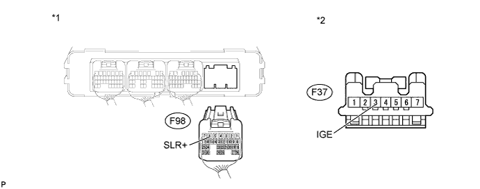
Standard Resistance Tester Connection Condition Specified Condition F37-3 (IGE) - F98-6 (SLR+) Always Below 1 Ω F37-3 (IGE) or F98-6 (SLR+) - Body ground Always 10 kΩ or higher Text in Illustration *1 Rear view of wire harness connector
(to Power Management Control ECU)
*2 Front view of wire harness connector
(to Steering Lock ECU)
NG
REPAIR OR REPLACE HARNESS OR CONNECTOR
OK 
REPLACE STEERING LOCK ECU (STEERING LOCK ACTUATOR ASSEMBLY) Click here
-
-
READ VALUE USING INTELLIGENT TESTER (DRIVER SIDE DOOR COURTESY SWITCH)
-
Use the Data List to check if the driver side door courtesy switch is functioning properly.
-
for LHD:
Main Body Tester Display Measurement Item/Range Normal Condition Diagnostic Note FL Door Courtesy SW Front door courtesy switch LH/
ON or OFF
ON: Front door courtesy switch LH ON
OFF: Front door courtesy switch LH OFF
- OK Front door courtesy switch LH is functioning properly. -
for RHD:
Main Body Tester Display Measurement Item/Range Normal Condition Diagnostic Note FR Door Courtesy SW Front door courtesy switch RH/
ON or OFF
ON: Front door courtesy switch RH ON
OFF: Front door courtesy switch RH OFF
- OK Front door courtesy switch RH is functioning properly.
-
NG
INSPECT LIGHTING SYSTEM Click here
OK
-
-
READ VALUE USING INTELLIGENT TESTER (S CODE)
-
Use the Data List to check if the S code certification is functioning properly.
Entry & Start Tester Display Measurement Item/Range Normal Condition Diagnostic Note S Code Check S code certification result/
NG or OK
NG: S code certification result abnormal
OK: S code certification result normal
- OK "OK" is displayed on the intelligent tester.
NG
REPLACE ID CODE BOX (IMMOBILISER CODE ECU) Click here
OK
-
-
READ VALUE USING INTELLIGENT TESTER (L CODE)
-
Use the Data List to check if the L code certification is functioning properly.
Entry & Start Tester Display Measurement Item/Range Normal Condition Diagnostic Note L Code Check L code certification result/
NG or OK
NG: L code certification result abnormal
OK: L code certification result normal
- OK "OK" is displayed on the intelligent tester.
NG
REPLACE ID CODE BOX (IMMOBILISER CODE ECU) Click here
OK
-
-
REPLACE STEERING LOCK ECU (STEERING LOCK ACTUATOR ASSEMBLY)
-
Replace the steering lock ECU (steering lock actuator assembly) Click here.
NEXT
-
-
CHECK STEERING LOCK RELEASED BY USUAL IGNITION
-
Turn the power switch on (IG).
-
Operate the steering wheel and check the steering lock condition.
OK Steering lock is released.
NG
REPLACE CERTIFICATION ECU (SMART KEY ECU ASSEMBLY)
OK
END (STEERING LOCK ECU (STEERING LOCK ACTUATOR ASSEMBLY) WAS DEFECTIVE)
-
-
REPLACE ID CODE BOX (IMMOBILISER CODE ECU)
-
Replace the ID code box (immobiliser code ECU).
NEXT
-
-
READ VALUE USING INTELLIGENT TESTER (S CODE)
-
Use the Data List to check if the S code certification is functioning properly.
Entry & Start Tester Display Measurement Item/Range Normal Condition Diagnostic Note S Code Check S code certification result/
NG or OK
NG: S code certification result abnormal
OK: S code certification result normal
- OK "OK" is displayed on the intelligent tester.
NG
REPLACE CERTIFICATION ECU (SMART KEY ECU ASSEMBLY)
OK
END (ID CODE BOX WAS DEFECTIVE)
-
-
REPLACE ID CODE BOX (IMMOBILISER CODE ECU)
-
Replace the ID code box (immobiliser code ECU).
NEXT
-
-
READ VALUE USING INTELLIGENT TESTER (L CODE)
-
Use the Data List to check if the L code certification is functioning properly.
Entry & Start Tester Display Measurement Item/Range Normal Condition Diagnostic Note L Code Check L code certification result/
NG or OK
NG: L code certification result abnormal
OK: L code certification result normal
- OK "OK" is displayed on the intelligent tester.
NG
REPLACE STEERING LOCK ECU (STEERING LOCK ACTUATOR ASSEMBLY) Click here
OK
END (ID CODE BOX WAS DEFECTIVE)
-