POWER TILT AND POWER TELESCOPIC STEERING COLUMN SYSTEM, Diagnostic DTC:B2610

| DTC Code | DTC Name |
|---|---|
| B2610 | Tilt Position Sensor or Tilt Motor Circuit Malfunction |
DESCRIPTION
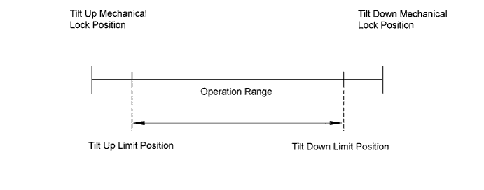
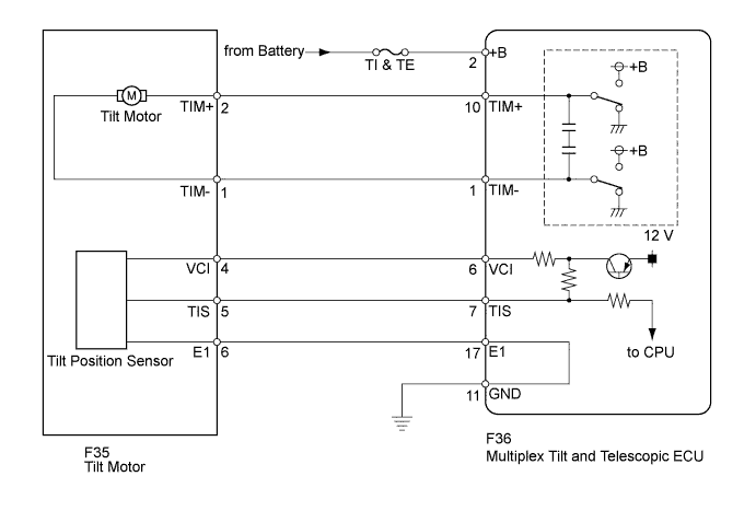
The tilt motor is operated by the power source voltage supplied from the multiplex tilt and telescopic ECU and makes the steering column tilt up and down. The tilt position sensor (Hall IC) in the tilt motor detects the tilt angle of the steering column and outputs a signal to the multiplex tilt and telescopic ECU based on that angle.
Tech Tips
Limit positions can be confirmed on the intelligent tester.
| DTC No. | Detection Item | Trouble Area |
|---|---|---|
| B2610 | Tilt operation stops within the operation range while operating. |
|
WIRING DIAGRAM
INSPECTION PROCEDURE
PROCEDURE
-
PERFORM ACTIVE TEST USING INTELLIGENT TESTER (TILT OPERATION)
-
Turn the power switch off.
-
Connect the intelligent tester to the DLC3.
-
Turn the power switch on (IG).
-
Turn the intelligent tester on.
-
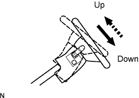
Check that the steering wheel tilts up and down. Enter the following menus: Chassis / Tilt & Telescopic / Active Test.
Tilt & Telescopic Tester Display Test Part Control Range Diagnostic Note Tilt Operation Tilt operation UP/DOWN - OK The steering wheel tilts up and down.
NG 
CHECK HARNESS AND CONNECTOR (MULTIPLEX TILT AND TELESCOPIC ECU - TILT POSITION SENSOR) Click here
OK 
-
-
CHECK HARNESS AND CONNECTOR (MULTIPLEX TILT AND TELESCOPIC ECU - BATTERY)
-
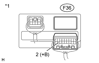
Text in Illustration *1 Rear view of wire harness connector
(to Multiplex Tilt and Telescopic ECU)
Disconnect the F36 multiplex tilt and telescopic ECU connector.
-
Measure the voltage according to the value(s) in the table below.
Standard Voltage Tester Connection Condition Specified Condition F36-2 (+B) - Body ground Always 11 to 14 V
NG 
REPAIR OR REPLACE HARNESS OR CONNECTOR
OK
-
-
CHECK HARNESS AND CONNECTOR (MULTIPLEX TILT AND TELESCOPIC ECU - BODY GROUND)
-
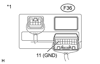
Text in Illustration *1 Rear view of wire harness connector
(to Multiplex Tilt and Telescopic ECU)
Measure the resistance according to the value(s) in the table below.
Standard Resistance Tester Connection Condition Specified Condition F36-11 (GND) - Body ground Always Below 1 Ω
NG
REPAIR OR REPLACE HARNESS OR CONNECTOR
OK
-
-
CHECK HARNESS AND CONNECTOR (MULTIPLEX TILT AND TELESCOPIC ECU - TILT MOTOR)
-
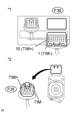
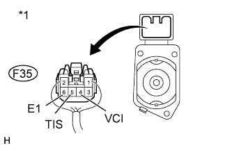
Text in Illustration *1 Rear view of wire harness connector
(to Multiplex Tilt and Telescopic ECU)
*2 Rear view of wire harness connector
(to Tilt Motor)
Disconnect the F36 multiplex tilt and telescopic ECU connector.
-
Disconnect the F35 tilt motor connector.
-
Measure the resistance according to the value(s) in the table below.
Standard Resistance Tester Connection Condition Specified Condition F36-10 (TIM+) - F35-2 (TIM+) Always Below 1 Ω F36-1 (TIM-) - F35-1 (TIM-) F36-10 (TIM+) - Body ground Always 10 kΩ or higher F36-1 (TIM-) - Body ground
NG
REPAIR OR REPLACE HARNESS OR CONNECTOR
OK
-
-
CHECK TILT MOTOR
-
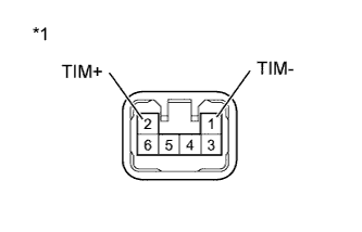
Text in Illustration *1 Component without harness connected
(Tilt Motor)
Apply 12 V battery voltage to the tilt motor connector.
Then check the steering wheel tilt operation.
OK Measurement Condition Specified Condition 12 V battery positive (+) lead → Terminal 1 (TIM-)
12 V battery negative (-) lead → Terminal 2 (TIM+)
The steering wheel tilts down. 12 V battery positive (+) lead → Terminal 2 (TIM+)
12 V battery negative (-) lead → Terminal 1 (TIM-)
The steering wheel tilts up. Result Result Proceed to NG A OK (for LHD) B OK (for RHD) C
B
REPLACE MULTIPLEX TILT AND TELESCOPIC ECU Click here
C
REPLACE MULTIPLEX TILT AND TELESCOPIC ECU Click here
A 
REPLACE STEERING COLUMN ASSEMBLY Click here
-
-
CHECK HARNESS AND CONNECTOR (MULTIPLEX TILT AND TELESCOPIC ECU - TILT POSITION SENSOR)
-
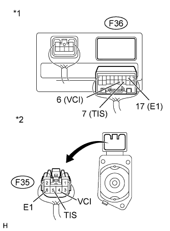
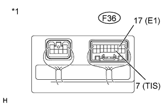
Text in Illustration *1 Rear view of wire harness connector
(to Multiplex Tilt and Telescopic ECU)
*2 Rear view of wire harness connector
(to Tilt Motor)
Disconnect the F36 multiplex tilt and telescopic ECU connector.
-
Disconnect the F35 tilt motor connector.
-
Measure the resistance according to the value(s) in the table below.
Standard Resistance Tester Connection Condition Specified Condition F36-6 (VCI) - F35-4 (VCI) Always Below 1 Ω F36-7 (TIS) - F35-5 (TIS) F36-17 (E1) - F35-6 (E1) F36-6 (VCI) - Body ground Always 10 kΩ or higher F36-7 (TIS) - Body ground F36-17 (E1) - Body ground
NG
REPAIR OR REPLACE HARNESS OR CONNECTOR
OK
-
-
CHECK HARNESS AND CONNECTOR (MULTIPLEX TILT AND TELESCOPIC ECU - BODY GROUND)
-

Text in Illustration *1 Rear view of wire harness connector
(to Multiplex Tilt and Telescopic ECU)
Measure the resistance according to the value(s) in the table below.
Standard Resistance Tester Connection Condition Specified Condition F36-11 (GND) - Body ground Always Below 1 Ω
NG
REPAIR OR REPLACE HARNESS OR CONNECTOR
OK
-
-
CHECK HARNESS AND CONNECTOR (VCI, TIS TERMINAL VOLTAGE)
-
Text in Illustration *1 Rear view of wire harness connector
(to Tilt Motor)
Reconnect the F36 multiplex tilt and telescopic ECU connector.
-
Measure the voltage according to the value(s) in the table below.
Standard Voltage Tester Connection Switch Condition Specified Condition F35-4 (VCI) - F35-6 (E1) switch on (IG) 8 to 16 V F35-5 (TIS) - F35-6 (E1)
NG
REPAIR OR REPLACE HARNESS OR CONNECTOR
OK
-
-
CHECK TILT POSITION SENSOR
-
Text in Illustration *1 Component with harness connected
(Multiplex Tilt and Telescopic ECU)
Reconnect the F35 tilt motor connector.
-
Measure the voltage according to the value(s) in the table below.
Standard Voltage Tester Connection Condition Specified Condition F36-7 (TIS) - F36-17 (E1) The steering wheel tilting up or tilting down Pulse generation
High: 8 to 16 V
Low: Below 1 V
Result Result Proceed to NG A OK (for LHD) B OK (for RHD) C
B
REPLACE MULTIPLEX TILT AND TELESCOPIC ECU Click here
C
REPLACE MULTIPLEX TILT AND TELESCOPIC ECU Click here
A
REPLACE STEERING COLUMN ASSEMBLY Click here
-