POWER TILT AND POWER TELESCOPIC STEERING COLUMN SYSTEM, Diagnostic DTC:B2603

| DTC Code | DTC Name |
|---|---|
| B2603 | Tilt and Telescopic Manual Switch Circuit Malfunction |
DESCRIPTION
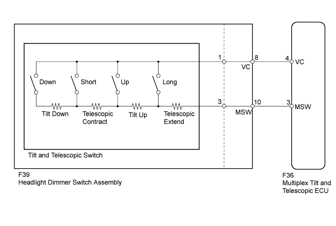
Different voltage values are input to the multiplex tilt and telescopic ECU by operating the tilt and telescopic switch. The multiplex tilt and telescopic ECU then judges which motor and in which direction that motor should be moved based on the voltage value.
| DTC No. | Detection Condition | Trouble Area |
|---|---|---|
| B2603 | When operating the tilt and telescopic switch, an abnormal voltage value is input to the multiplex tilt and telescopic ECU. |
|
-
*1: for LHD, RHD Light control switch LH side type
-
*2: for RHD Light control switch RH side type
WIRING DIAGRAM
-
for LHD, RHD Light Control Switch LH Side Type:
-
for RHD Light Control Switch RH Side Type:

INSPECTION PROCEDURE
PROCEDURE
-
READ VALUE USING INTELLIGENT TESTER (TILT UP/DOWN SWITCH, TELESCOPIC SHORT/LONG SWITCH)
-
Turn the power switch off.
-
Connect the intelligent tester to the DLC3.
-
Turn the power switch on (IG).
-
Turn the intelligent tester on.
-
Check the tilt and telescopic manual switch. Enter the following menus: Chassis / Tilt & Telescopic / Data List.
Tilt & Telescopic Tester Display Measurement Item/Range Normal Condition Diagnostic Note Telesco Short Switch Input state of telescopic short by manual switch/
OFF or ON
OFF: Telescopic short not activated by manual switch
ON: Telescopic short activated by manual switch
- Telesco Long Switch Input state of telescopic long by manual switch/
OFF or ON
OFF: Telescopic long not activated by manual switch
ON: Telescopic long activated by manual switch
- Tilt Down Switch Input state of tilt down by manual switch/
OFF or ON
OFF: Tilt down not activated by manual switch
ON: Tilt down activated by manual switch
- Tilt Up Switch Input state of tilt up by manual switch//
OFF or ON
OFF: Tilt up not activated by manual switch
ON: Tilt up activated by manual switch
- OK "ON" is displayed on the intelligent tester screen when each switch is turned on. "OFF" is displayed on the intelligent tester screen when each switch is turned off.
NG 
CHECK HARNESS AND CONNECTOR (MULTIPLEX TILT AND TELESCOPIC ECU - TILT AND TELESCOPIC SWITCH) Click here
OK 
-
-
CONFIRM DTC
-
Clear the DTC Click here.
-
Check for DTCs Click here.
Result Result Proceed to DTC is not output. A DTC is output. (for LHD) B DTC is output. (for RHD) C
B 
REPLACE MULTIPLEX TILT AND TELESCOPIC ECU Click here
C
REPLACE MULTIPLEX TILT AND TELESCOPIC ECU Click here
A 
USE SIMULATION METHOD TO CHECK Click here
-
-
CHECK HARNESS AND CONNECTOR (MULTIPLEX TILT AND TELESCOPIC ECU - TILT AND TELESCOPIC SWITCH)
-
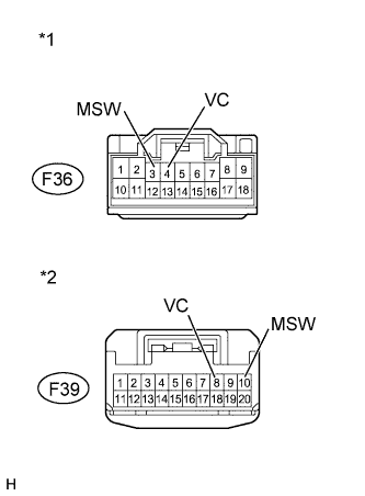
Text in Illustration *1 Front view of wire harness connector
(to Multiplex Tilt and Telescopic ECU)
*2 Front view of wire harness connector
(to Headlight Dimmer Switch Assembly)
for LHD, RHD Light control switch LH side type:
-
Disconnect the F36 multiplex tilt and telescopic ECU connector.
-
Disconnect the F39 headlight dimmer switch assembly connector.
-
Measure the resistance according to the value(s) in the table below.
Standard Resistance Tester Connection Condition Specified Condition F36-4 (VC) - F39-8 (VC) Always Below 1 Ω F36-3 (MSW) - F39-10 (MSW) F39-8 (VC) - Body ground Always 10 kΩ or higher F39-10 (MSW) - Body ground
-
-
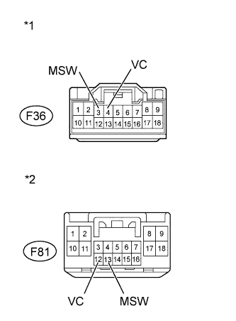
Text in Illustration *1 Front view of wire harness connector
(to Multiplex Tilt and Telescopic ECU)
*2 Front view of wire harness connector
(to Windshield Wiper Switch Assembly)
for RHD Light control switch RH side type:
-
Disconnect the F36 multiplex tilt and telescopic ECU connector.
-
Disconnect the F81 windshield wiper switch assembly connector.
-
Measure the resistance according to the value(s) in the table below.
Standard Resistance Tester Connection Condition Specified Condition F36-4 (VC) - F81-12 (VC) Always Below 1 Ω F36-3 (MSW) - F81-13 (MSW) F81-12 (VC) - Body ground Always 10 kΩ or higher F81-13 (MSW) - Body ground
-
NG
REPAIR OR REPLACE HARNESS OR CONNECTOR
OK
-
-
CHECK MULTIPLEX TILT AND TELESCOPIC ECU (VC TERMINAL VOLTAGE)
-
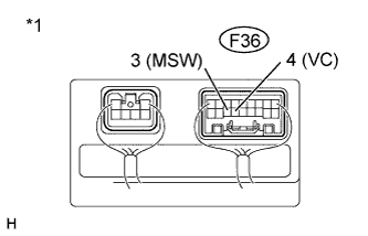
Text in Illustration *1 Component with harness connected
(Multiplex Tilt and Telescopic ECU)
Reconnect the F36 multiplex tilt and telescopic ECU connector.
-
Measure the voltage according to the value(s) in the table below.
Standard Voltage Tester Connection Switch Condition Specified Condition F36-4 (VC) - F36-3 (MSW) Power switch on (IG) 4.9 to 5.1 V Result Result Proceed to OK A NG (for LHD) B NG (for RHD) C
B
REPLACE MULTIPLEX TILT AND TELESCOPIC ECU Click here
C
REPLACE MULTIPLEX TILT AND TELESCOPIC ECU Click here
A
-
-
CHECK TILT AND TELESCOPIC SWITCH
-
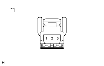
Text in Illustration *1 Component without harness connected
(Tilt and Telescopic Switch)
Remove the tilt and telescopic switch Click here.
-
Measure the resistance according to the value(s) in the table below.
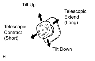
Standard Resistance Tester Connection Switch Condition Specified Condition 1 - 3 Tilt up 342 to 378 Ω Tilt down 1890.5 to 2089.5 Ω Telescopic contract 750.5 to 829.5 Ω Telescopic extend 152 to 168 Ω Result Result Proceed to NG A OK (for LHD, RHD Light control switch LH side type) B OK (for RHD Light control switch RH side type) C
B
REPLACE HEADLIGHT DIMMER SWITCH ASSEMBLY Click here
C
REPLACE WINDSHIELD WIPER SWITCH ASSEMBLY Click here
A
REPLACE TILT AND TELESCOPIC SWITCH Click here
-