POWER STEERING SYSTEM, Diagnostic DTC:C1566

| DTC Code | DTC Name |
|---|---|
| C1566 | Lost Communication with PSOK Signal of DC / DC Converter |
DESCRIPTION
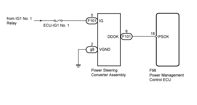
Based on the WDD signal (power steering converter assembly condition notification signal) from the power steering converter assembly, the power steering ECU performs various processes. Based on the PSOK signal (EPS assist permission signal) from the power management control ECU, the power steering converter assembly supplies a high voltage power supply to the power steering ECU. As a fail-safe function, while the system is malfunctioning, power assistance is limited/stopped.
| DTC No. | DTC Detection Condition | Trouble Area |
|---|---|---|
| C1566 | PSOK signal communication error |
|
WIRING DIAGRAM
INSPECTION PROCEDURE
Note
-
If the power steering ECU has been replaced with a new one, perform the rotation angle sensor initialization and torque sensor zero point calibration Click here.
-
Inspect the fuses for circuits related to this system before performing the following inspection procedure.
PROCEDURE
-
CHECK FOR DTC (HYBRID CONTROL SYSTEM)
-
Check for DTCs in the hybrid control system Click here.
Result Result Proceed to DTC P3086-184 or P3087-183 is not output A DTC P3086-184 or P3087-183 is output B
B 
GO TO HYBRID CONTROL SYSTEM (DIAGNOSTIC TROUBLE CODE CHART) Click here
A 
-
-
CHECK HARNESS AND CONNECTOR (POWER MANAGEMENT CONTROL ECU - POWER STEERING CONVERTER)
-
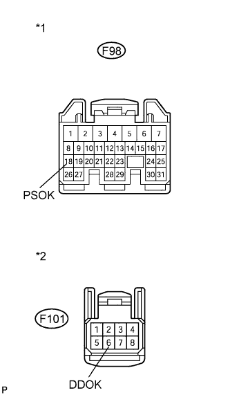
Text in Illustration *1 Front view of wire harness connector
(to Power Management Control ECU)
*2 Front view of wire harness connector
(to Power Steering Converter Assembly)
Disconnect the F98 power management control ECU connector.
-
Disconnect the F101 power steering converter connector.
-
Measure the resistance according to the value(s) in the table below.
Standard Resistance Tester Connector Condition Specified Condition F98-18 (PSOK) - F101-6 (DDOK) Always Below 1 Ω F98-18 (PSOK) or F101-6 (DDOK) - Body ground Always 10 kΩ or higher
NG
REPAIR OR REPLACE HARNESS OR CONNECTOR
OK
-
-
CHECK HARNESS AND CONNECTOR (POWER STEERING CONVERTER POWER SUPPLY)
-
Reconnect the F98 power management control ECU connector.
-
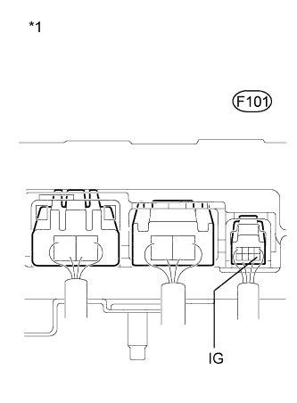
Text in Illustration *1 Component with harness connected
(Power Steering Converter Assembly)
Reconnect the F101 power steering converter assembly connector.
-
Turn the power switch on (IG).
-
Measure the voltage according to the value(s) in the table below.
Standard Voltage Tester Connector Switch Condition Specified Condition F101-5 (IG) - Body ground Power switch on (IG) 11 to 14 V -
Turn the power switch off.
-
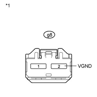
Text in Illustration *1 Front view of wire harness connector
(to Power Steering Converter Assembly)
Disconnect the g8 power steering converter assembly connector.
-
Measure the resistance according to the value(s) in the table below.
Standard Resistance Tester Connector Condition Specified Condition g8-2 (VGND) - Body ground Always Below 1 Ω
NG
REPAIR OR REPLACE HARNESS OR CONNECTOR
OK
-
-
REPLACE POWER STEERING CONVERTER ASSEMBLY
-
Replace the power steering converter assembly with a new or normally functioning one Click here.
NEXT
-
-
CHECK FOR DTC (POWER STEERING SYSTEM)
-
Check for DTCs in the power steering system Click here.
Result Result Proceed to DTC C1566 is not output A DTC C1566 is output B
B
REPLACE POWER STEERING ECU Click here
A 
END
-