POWER STEERING SYSTEM, Diagnostic DTC:C1564, C1565

| DTC Code | DTC Name |
|---|---|
| C1564 | Lost Communication with WDD Signal of DC / DC Converter |
| C1565 | Lost Communication with LDD/ASST Signal of DC / DC Converter |
DESCRIPTION
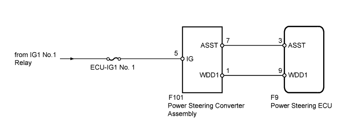
Based on the WDD signal (power steering converter assembly condition notification signal) from the power steering converter assembly, the power steering ECU processes and outputs signals. Based on the ASST signal (EPS demand signal) from the power steering ECU, the power steering converter assembly processes and outputs signals. As a fail-safe function, when the system is malfunctioning, power assistance is limited.
| DTC No. | DTC Detection Condition | Trouble Area |
|---|---|---|
| C1564 | WDD signal communication error |
|
| C1565 | ASST signal communication error |
|
WIRING DIAGRAM
INSPECTION PROCEDURE
Note
-
If the power steering ECU has been replaced with a new one, perform the rotation angle sensor initialization and torque sensor zero point calibration Click here.
-
Inspect the fuses for circuits related to this system before performing the following inspection procedure.
PROCEDURE
-
CHECK HARNESS AND CONNECTOR (POWER STEERING ECU - POWER STEERING CONVERTER)
-
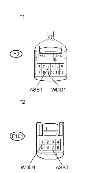
Text in Illustration *1 Front view of wire harness connector
(to Power Steering ECU)
*2 Front view of wire harness connector
(to Power Steering Converter Assembly)
Disconnect the F9 power steering ECU connector.
-
Disconnect the F101 power steering converter assembly connector.
-
Measure the resistance according to the value(s) in the table below.
Standard Resistance Tester Connection Condition Specified Condition F9-3 (ASST) - F101-7 (ASST) Always Below 1 Ω F9-9 (WDD1) - F101-1 (WDD1) F9-3 (ASST) or F101-7 (ASST) - Body ground Always 10 kΩ or higher F9-9 (WDD1) or F101-1 (WDD1) - Body ground
NG 
REPAIR OR REPLACE HARNESS OR CONNECTOR
OK 
-
-
CHECK HARNESS AND CONNECTOR (POWER STEERING CONVERTER POWER SUPPLY)
-

Text in Illustration *1 Front view of wire harness connector
(to Power Steering Converter Assembly)
Measure the voltage according to the value(s) in the table below.
Standard Voltage Tester Connection Switch Condition Specified Condition F101-5 (IG) - Body ground Power switch on (IG) 11 to 14 V
NG
REPAIR OR REPLACE HARNESS OR CONNECTOR
OK
-
-
REPLACE POWER STEERING CONVERTER ASSEMBLY
-
Replace the power steering converter assembly with a new or known good one Click here.
NEXT
-
-
CHECK FOR DTC
-
Check for DTCs Click here.
Result Result Proceed to DTC C1564 and C1565 are not output. A DTC C1564 or C1565 is output. B
B
REPLACE POWER STEERING ECU Click here
A 
END
-