POWER STEERING SYSTEM, Diagnostic DTC:C1562

| DTC Code | DTC Name |
|---|---|
| C1562 | DC / DC Converter PIG Power Supply Voltage |
DESCRIPTION
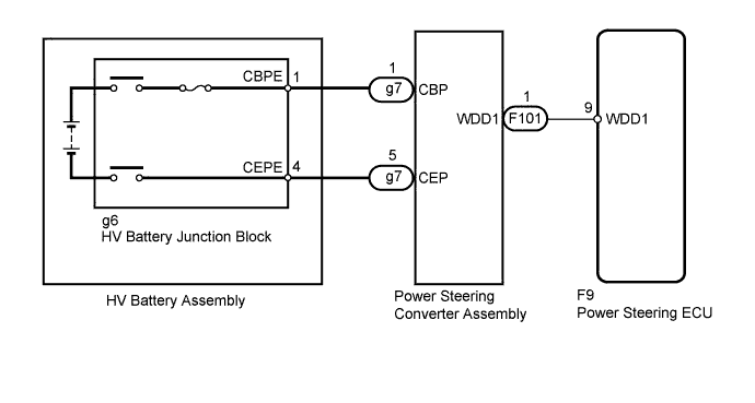
If an HV battery power supply malfunction signal from the power steering converter assembly is input to the power steering ECU, this DTC is stored and the P/S warning light illuminates. At this time, as a fail-safe function, power assistance is limited/stopped.
| DTC No. | DTC Detection Condition | Trouble Area |
|---|---|---|
| C1562 | Malfunction of power steering converter power supply from HV battery |
|
WIRING DIAGRAM
INSPECTION PROCEDURE
CAUTION:
-
Before disconnecting the high-voltage connector of the power steering converter assembly, take safety precautions such as wearing insulated gloves and removing the service plug grip to prevent electrical shocks. After removing the service plug grip, put it in your pocket to prevent other technicians from accidentally reconnecting it while you are working on the high-voltage system.
-
After disconnecting the service plug grip, wait for at least 10 minutes before touching any of the high-voltage connectors or terminals. After waiting for 10 minutes, check the voltage at the terminals in the inspection point in the inverter with converter assembly. The voltage should be 0 V before beginning work.
Tech Tips
-
Waiting for at least 10 minutes is required to discharge the high-voltage capacitor inside the inverter with converter assembly.
-
When measuring insulation resistance using a megohmmeter, set the megohmmeter to 500 V.
PROCEDURE
-
CHECK FOR DTC (HYBRID CONTROL SYSTEM)
-
Check for DTCs in the hybrid control system Click here.
Result Result Proceed to DTC is not output A DTC is output B
B 
GO TO HYBRID CONTROL SYSTEM Click here
A 
-
-
CHECK HARNESS AND CONNECTOR (POWER STEERING CONVERTER - HV BATTERY JUNCTION BLOCK)
CAUTION:
Be sure to wear insulated gloves.
-
Check that the service plug grip is not installed.
-
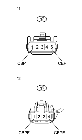
Text in Illustration *1 Front view of wire harness connector
(to Power Steering Converter Assembly)
*2 Front view of wire harness connector
(to HV Battery Junction Block)
Disconnect the g7 power steering converter assembly connector.
-
Disconnect the g6 HV battery junction block connector.
-
Measure the resistance according to the value(s) in the table below.
Standard Resistance Tester Connector Switch Condition Specified Condition g7-1 (CBP) - g6-1 (CBPE) Power switch off Below 1 Ω g7-5 (CEP) - g6-4 (CEPE) -
Using a megohmmeter set to 500 V, measure the resistance according to the value(s) in the table below.
Note
Be sure to set the megohmmeter to 500 V when performing this test. Using a setting higher than 500 V can result in damage to the component being inspected.
Standard Resistance Tester Connector Switch Condition Specified Condition g6-1 (CBPE) or g6-4 (CEPE) - Body ground Power switch off 10 MΩ or higher g6-1 (CBPE) - g6-4 (CEPE)
NG
REPAIR OR REPLACE HARNESS OR CONNECTOR
OK 
REPLACE POWER STEERING CONVERTER ASSEMBLY Click here
-