POWER STEERING SYSTEM, Diagnostic DTC:C1528

| DTC Code | DTC Name |
|---|---|
| C1528 | Motor Rotation Angle Sensor Malfunction |
DESCRIPTION
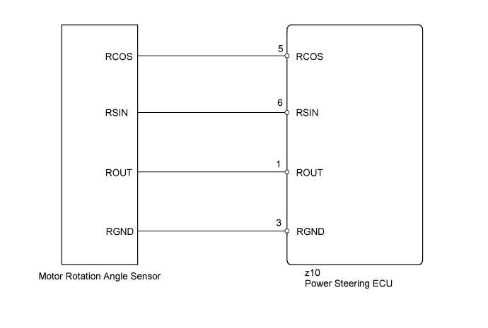
The motor rotation angle sensor detects the motor rotation angle and sends this information to the power steering ECU.
| DTC No. | DTC Detection Condition | Trouble Area |
|---|---|---|
| C1528 | Motor rotation angle sensor malfunction |
|
WIRING DIAGRAM
INSPECTION PROCEDURE
Note
If the power steering ECU and steering column assembly have been replaced, perform the rotation angle sensor initialization and torque sensor zero point calibration Click here.
PROCEDURE
-
CHECK CONNECTOR CONNECTION CONDITION
-
Check the installation condition of the motor rotation angle sensor connector.
OK The motor rotation angle sensor connector is securely connected to the power steering ECU.
NG 
CONNECT CONNECTOR
OK 
-
-
READ VALUE USING INTELLIGENT TESTER (MOTOR ROTATION ANGLE SENSOR)
-
Turn the power switch off.
-
Connect the intelligent tester to the DLC3.
-
Turn the power switch on (IG).
-
Turn the intelligent tester on.
-
Enter the following menus: Chassis / EMPS / Data List.
-
Select the item "Motor Rotation Angle" in the Data List and read the value displayed on the intelligent tester.
EMPS Tester Display Measurement Item/Range Normal Condition Diagnostic Note Motor Rotation Angle Motor rotation angle/
Min.: 0 deg
Max.: 360 deg
During steering operation, motor rotation angle value changes from 0 to 360° The power switch on (READY) and steering wheel is being turned. OK During steering operation, motor rotation angle value changes from 0 to 360°.
NG 
CHECK STEERING COLUMN ASSEMBLY Click here
OK 
REPLACE POWER STEERING ECU Click here
-
-
CHECK STEERING COLUMN ASSEMBLY
-
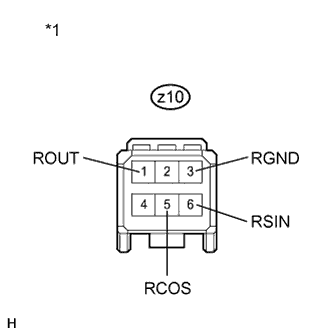
Text in Illustration *1 Front view of wire harness connector
(to Power Steering ECU)
Disconnect the z10 power steering ECU connector.
-
Measure the resistance according to the value(s) in the table below.
Standard Resistance Tester Connection Condition Specified Condition z10-6 (RSIN) - z10-3 (RGND) Always 75.2 to 112.8 Ω z10-1 (ROUT) - z10-3 (RGND) Always 27.6 to 41.4 Ω z10-5 (RCOS) - z10-3 (RGND) Always 73.2 to 110.8 Ω
NG
REPLACE STEERING COLUMN ASSEMBLY Click here
OK
REPLACE POWER STEERING ECU Click here
-