POWER STEERING SYSTEM, Diagnostic DTC:C1569

| DTC Code | DTC Name |
|---|---|
| C1569 | Battery Power Supply Voltage Malfunction |
DESCRIPTION
As a fail-safe function, when the battery power supply voltage is malfunctioning, power assistance is limited/stopped.
| DTC No. | DTC Detection Condition | Trouble Area |
|---|---|---|
| C1569 | Malfunction in auxiliary battery power supply voltage. |
|
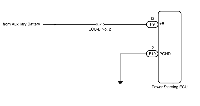
WIRING DIAGRAM
INSPECTION PROCEDURE
Note
-
If the power steering ECU has been replaced with a new one, perform the rotation angle sensor initialization and torque sensor zero point calibration Click here.
-
Inspect the fuses for circuits related to this system before performing the following inspection procedure.
PROCEDURE
-
CHECK HARNESS AND CONNECTOR (POWER STEERING ECU - BATTERY AND BODY GROUND)
-
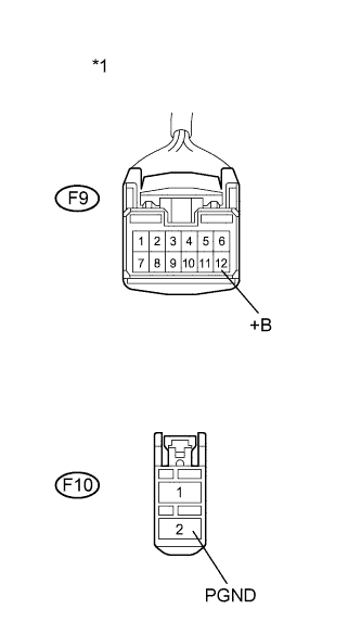
Text in Illustration *1 Front view of wire harness connector
(to Power Steering ECU)
Disconnect the F9 and F10 power steering ECU connector.
-
Measure the voltage according to the value(s) in the table below.
Standard Voltage Tester Connection Condition Specified Condition F9-12 (+B) - Body ground Always 11 to 14 V -
Measure the resistance according to the value(s) in the table below.
Standard Resistance Tester Connection Condition Specified Condition F10-2 (PGND) - Body ground Always Below 1 Ω
NG 
REPAIR OR REPLACE HARNESS OR CONNECTOR
OK 
REPLACE POWER STEERING ECU Click here
-