POWER STEERING SYSTEM TERMINALS OF ECU

-
CHECK POWER STEERING ECU
Tech Tips
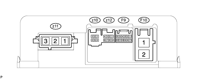
As connector z11 uses a lock lever, each terminal cannot be checked while the connector is still connected to the power steering ECU.
Terminal No. (Symbol) Wiring Color Terminal Description z11-1 (MV) W V phase motor output z11-2 (MU) B U phase motor output z11-3 (MW) R W phase motor output
-
Measure the voltage and resistance according to the value(s) in the table below.
Note
When the P/S warning light is illuminated during a malfunction, the fail-safe function may cause the voltage of the power steering ECU terminals to become 0 V.
Terminal No. (Symbol) Wiring Color Terminal Description Condition Specified Condition F10-1 (PIG) - F10-2 (PGND) W - B Power source Always 25 to 50 V F10-2 (PGND) - Body ground B - Body ground Power ground Always Below 1 Ω F9-1 (CANH) - F9-7 (CANL) G - R CAN communication line Power switch off 54 to 69 Ω F9-6 (IG) - F10-2 (PGND) Y - B IG power source Power switch on (IG) 11 to 14 V F9-3 (ASST) - F10-2 (PGND) G - B EPS demand signal Always Pulse generation F9-9 (WDD1) - F10-2 (PGND) P - B Power steering converter condition notification signal Always Pulse generation F9-12 (+B) - F10-2 (PGND) B - B +B power source Always 11 to 14 V z10-1 (ROUT) - F10-2 (PGND) (Not available) - B Rotation angle sensor excitation output signal Power switch on (READY), steering wheel being turned -2.42 to 2.42 V z10-3 (RGND) - F10-2 (PGND) (Not available) - B Rotation angle sensor excitation circuit GND Always Below 1 Ω z10-5 (RCOS) - F10-2 (PGND) (Not available) - B Rotation angle sensor COS aspect output signal Power switch on (READY), steering wheel being turned -0.73 to 0.73 V z10-6 (RSIN) - F10-2 (PGND) (Not available) - B Rotation angle sensor SIN aspect output signal Power switch on (READY), steering wheel being turned -0.73 to 0.73 V z12-5 (TRQ1) - z12-8 (TRQG) (Not available) Torque sensor signal Power switch on (READY), steering wheel not turned (without load) 2.3 to 2.7 V Power switch on (READY), steering wheel turned to right with vehicle stopped 2.5 to 3.8 V Power switch on (READY), steering wheel turned to left with vehicle stopped 1.2 to 2.5 V z12-6 (TRQV) - z12-8 (TRQG) (Not available) Torque sensor voltage source Power switch on (IG) 4.5 to 5.5 V z12-7 (TRQ2) - z12-8 (TRQG) (Not available) Torque sensor signal Power switch on (READY), steering wheel not turned (without load) 2.3 to 2.7 V Power switch on (READY), steering wheel turned to right with vehicle stopped 1.2 to 2.5 V Power switch on (READY), steering wheel turned to left with vehicle stopped 2.5 to 3.8 V z12-8 (TRQG) - Body ground (Not available) - Body ground Torque sensor ground Always Below 1 Ω If the result is not as specified, the ECU may have a malfunction.
-
-
POWER STEERING CONVERTER
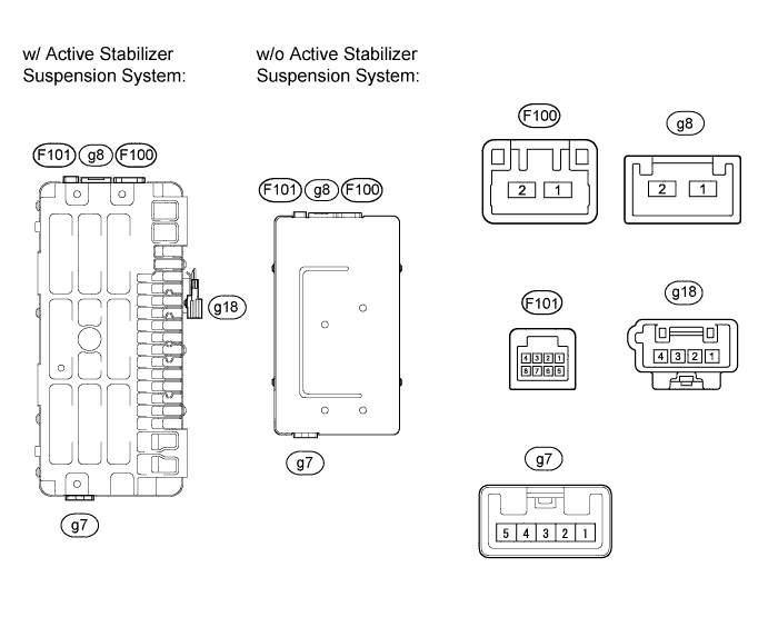
Terminal No. (Symbol) Wiring Color Terminal Description F101-1 (WDD1) P Power steering converter condition signal output to power steering ECU F101-2 (WDD3)* L Power steering converter condition signal output to active stabilizer control ECU F101-3 (DRSF)* B 46 V power supply stop signal input from front active stabilizer control ECU F101-4 (DRSR)* R 46 V power supply stop signal input from rear active stabilizer control ECU F101-5 (IG) Y IG power source F101-6 (DDOK) GR High voltage use permission signal input from hybrid vehicle control ECU F101-7 (ASST) G 46 V power supply output from power steering ECU g18-3 (SHLD)* B 46 V power supply output to front active stabilizer control ECU shielded line ground g18-4 (GND)* B 46 V power supply output to rear active stabilizer control ECU shielded line ground g8-1 (PIG) B Backup power supply input (12 V) of power steering system g8-2 (VGND) W Ground F100-1 (VOT1) W 46 V power supply output to power steering ECU F100-2 (VOT2)* B 46 V power supply output to active stabilizer control ECU g7-1 (CBP) R HV battery positive (+) power supply g7-5 (CEP) L HV battery negative (-) power supply
-
*: w/ Active stabilizer Suspension system
-