REAR BRAKE INSTALLATION

Tech Tips
-
Use the same procedure for the RH side and LH side.
-
The following procedure is for the LH side.
-
INSTALL REAR DISC
-
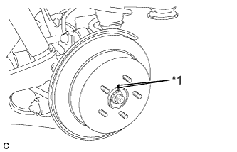
Text in Illustration *1 Matchmark Align the matchmarks and install the rear disc.
Note
When replacing the rear disc with a new one, select the installation position where the rear disc has minimal runout.
-
-
INSTALL PARKING BRAKE SHOE ADJUSTING HOLE PLUG
-
Install the parking brake shoe adjusting hole plug.
-
-
INSTALL REAR DISC BRAKE CYLINDER MOUNTING
-
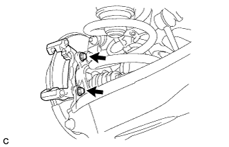
Install the rear disc brake cylinder mounting to the rear axle carrier sub-assembly with the 2 bolts.
- Torque:
- 78 N*m { 799 kgf*cm, 58 ft.*lbf }
-
-
INSTALL REAR DISC BRAKE BUSHING DUST BOOT
-
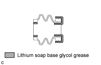
Apply a light layer of lithium soap base glycol grease to the entire circumference of 2 new rear disc brake bushing dust boots.
Tech Tips
Apply at least 0.3 g (0.01 oz.) of lithium soap base glycol grease to each rear disc brake bushing dust boot.
-
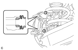
Install the 2 rear disc brake bushing dust boots to the rear disc brake cylinder mounting.
-
-
INSTALL NO. 2 REAR DISC BRAKE CYLINDER SLIDE PIN
-

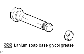
Apply a light layer of lithium soap base glycol grease to the sliding part and the seal surface of the No. 2 rear disc brake cylinder slide pin.
-
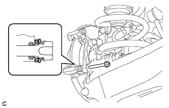
Install the No. 2 rear disc brake cylinder slide pin to the rear brake cylinder mounting.
-
Push the No. 2 rear disc brake cylinder slide pin into the rear disc brake bushing dust boot to align them.
-
-
INSTALL REAR DISC BRAKE CYLINDER SLIDE BUSHING
-
Apply a light layer of lithium soap base glycol grease to the contact surface of the No. 1 rear disc brake cylinder slide pin.
-
Install a new rear disc brake cylinder slide bushing to the No. 1 rear disc brake cylinder slide pin.
-
-
INSTALL NO. 1 REAR DISC BRAKE CYLINDER SLIDE PIN
-
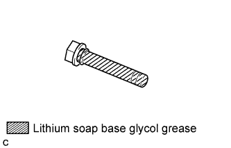
Apply a light layer of lithium soap base glycol grease to the sliding part and the seal surface of the No. 1 rear disc brake cylinder slide pin.
-
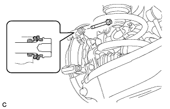
Install the No. 1 rear disc brake cylinder slide pin to the rear disc brake cylinder mounting.
-
Push the No. 1 rear disc brake cylinder slide pin into the rear disc brake bushing dust boot to align them.
-
-
INSTALL REAR DISC BRAKE PAD SUPPORT PLATE
-
Install the 2 No. 1 rear disc brake pad support plates and 2 No. 2 rear disc brake pad support plates to the rear disc brake cylinder mounting.
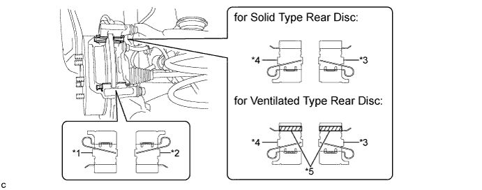
Text in Illustration for Solid Type Rear Disc for Ventilated Type Rear Disc *1 No. 1 Rear Disc Brake Pad Support Plate No. 1 Rear Disc Brake Pad Support Plate *2 No. 2 Rear Disc Brake Pad Support Plate No. 2 Rear Disc Brake Pad Support Plate *3 No. 1 Rear Disc Brake Pad Support Plate No. 1 Rear Disc Brake Pad Support Plate with Tape *4 No. 2 Rear Disc Brake Pad Support Plate No. 2 Rear Disc Brake Pad Support Plate with Tape *5 - Tape Note
-
Be sure to install the No. 1 rear disc brake pad support plates and the No. 2 rear disc brake pad support plates to the correct positions and directions.
-
The rear disc brake pad support plates with tape is installed in the upper portion (for ventilated type rear disc brake).
-
-
-
INSTALL PAD WEAR INDICATOR PLATE
-
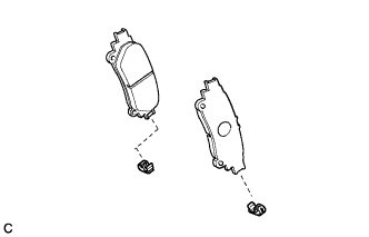
Install the 2 pad wear indicators to the rear disc brake pads.
Note
Install the pad wear indicators and rear anti-squeal shims in the correct positions and directions.
-
-
INSTALL REAR DISC BRAKE ANTI-SQUEAL SHIM
-
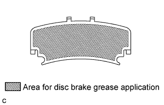
Apply disc brake grease to the inside of the 2 rear disc brake anti-squeal shims as shown in the illustration.
Note
-
When replacing worn pads, the rear disc brake anti-squeal shims must be replaced together with the pads.
-
Install the shims in the correct positions and directions.
-
Apply disc brake grease to the area that contacts the rear disc brake anti-squeal shims.
-
Disc brake grease can come out slightly from the area where the rear disc brake anti-squeal shims are installed.
-
Make sure that disc brake grease is not applied onto the lining surface.
-
-
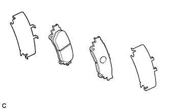
Install the rear disc brake anti-squeal shims to each of the 2 rear disc brake pads.
-
-
INSTALL REAR DISC BRAKE PAD
-
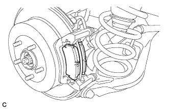
Install the 2 rear disc brake pads to the rear disc brake cylinder mounting.
-
-
INSTALL REAR DISC BRAKE CYLINDER ASSEMBLY
-
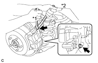
Text in Illustration *1 Hold *2 Turn Hold the 2 rear disc brake cylinder slide pins and install the rear disc brake cylinder assembly to the rear disc brake cylinder mounting with the 2 bolts.
- Torque:
- 27 N*m { 270 kgf*cm, 20 ft.*lbf }
-
-
CONNECT REAR FLEXIBLE HOSE
-
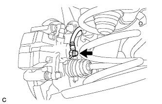
Connect the rear flexible hose to the rear disc brake cylinder assembly with the union bolt and a new gasket.
- Torque:
- 30 N*m { 306 kgf*cm, 22 ft.*lbf }
-
-
BLEED BRAKE LINE
-
Bleed brake line.
-
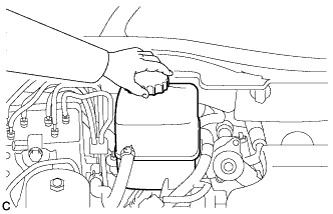
Remove the brake master cylinder reservoir filler cap assembly.
-
Add brake fluid into the reservoir between MAX and MIN level on the brake fluid reservoir.
Brake fluid SAE J1703 or FMVSS No. 116 DOT3 -
Connect the intelligent tester to the DLC3 and turn the power switch on (IG).
-
Turn the intelligent tester on and enter the following menus: Chassis / ABS/VSC/TRC / Utility / Air Bleeding.
-
Select the "Usual air bleeding / All Line" and bleed brake line according to the intelligent tester display.
-
After air bleeding, tighten each bleeder plug.
- Torque:
- front bleeder plug
- 8.3 N*m { 85 kgf*cm, 73 in.*lbf }
- rear bleeder plug
- 11 N*m { 110 kgf*cm, 8 ft.*lbf }
-
-
Clear the DTCs Click here.
-
Turn the intelligent tester off and turn the power switch off.
-
Inspect for brake fluid leaks.
-
Adjust the brake fluid level in the reservoir Click here.
-
-
ADJUST PARKING BRAKE SHOE CLEARANCE AND PARKING BRAKE PEDAL TRAVEL (for LHD)
-
Remove the No. 1 instrument panel under cover sub-assembly Click here.
-
Completely release the parking brake pedal.
-
Text in Illustration *1 Lock Nut *2 Adjusting Nut Loosen the lock nut and the adjusting nut to completely release the parking brake cable.
-
Remove the rear wheels.
-
Temporarily install the hub nuts to the hub bolts.
Tech Tips
Securely install the hub nuts to the rear disc.
-
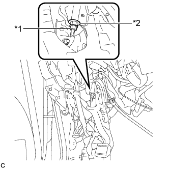
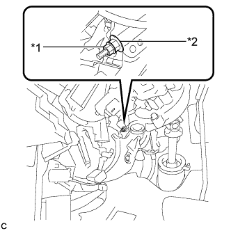
Remove the parking brake shoe adjusting hole plug.
-
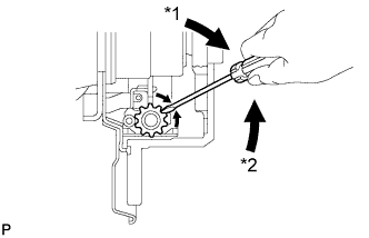
Text in Illustration *1 Expand *2 Contract Turn the shoe adjuster and expand the shoe until the disc locks.
-
Turn and contract the shoe adjuster until the disc can rotate smoothly.
Standard Returns 8 notches. -
Check that there is no brake drag against the shoe.
-
Install the parking brake shoe adjusting hole plug.
-
Turn the adjusting nut until the parking brake pedal travel is corrected to be within the specified range.
Parking brake pedal travel 7 to 10 notches at 300 N (31 kgf, 67.5 lbf) -
Text in Illustration *1 Lock Nut *2 Adjusting Nut Using a wrench or an equivalent tool, hold the adjusting nut and tighten the lock nut.
- Torque:
- 7.0 N*m { 71 kgf*cm, 62 in.*lbf }
-
Operate the parking brake pedal 3 to 4 times, and check the parking brake pedal travel.
-
Check that there is no brake drag against the shoe.
-
Remove the hub nuts from the hub bolts.
-
Install the rear wheels.
- Torque:
- 103 N*m { 1050 kgf*cm, 76 ft.*lbf }
-
Install the No. 1 instrument panel under cover sub-assembly Click here.
-
-
ADJUST PARKING BRAKE SHOE CLEARANCE AND PARKING BRAKE PEDAL TRAVEL (for RHD)
-
Remove the No. 1 instrument panel under cover sub-assembly Click here.
-
Completely release the parking brake pedal.
-
Text in Illustration *1 Lock Nut *2 Adjusting Nut Loosen the lock nut and the adjusting nut to completely release the parking brake cable.
-
Remove the rear wheels.
-
Temporarily install the hub nuts to the hub bolts.
Tech Tips
Securely install the hub nuts to the rear disc.
-
Remove the shoe adjusting hole plug.
-
Text in Illustration *1 Expand *2 Contract Turn the shoe adjuster and expand the shoe until the disc locks.
-
Turn and contract the shoe adjuster until the disc can rotate smoothly.
Standard Returns 8 notches. -
Check that there is no brake drag against the shoe.
-
Install the shoe adjusting hole plug.
-
Turn the adjusting nut until the parking brake pedal travel is corrected to be within the specified range.
Parking brake pedal travel 7 to 10 notches at 300 N (31 kgf, 67.5 lbf) -
Text in Illustration *1 Lock Nut *2 Adjusting Nut Using a wrench or an equivalent tool, hold the adjusting nut and tighten the lock nut.
- Torque:
- 7.0 N*m { 71 kgf*cm, 62 in.*lbf }
-
Operate the parking brake pedal 3 to 4 times, and check the parking brake pedal travel.
-
Check that there is no brake drag against the shoe.
-
Remove the hub nuts from the hub bolts.
-
Install the rear wheels.
- Torque:
- 103 N*m { 1050 kgf*cm, 76 ft.*lbf }
-
Install the No. 1 instrument panel under cover sub-assembly Click here.
-
-
INSTALL REAR WHEEL
- Torque:
- 103 N*m { 1050 kgf*cm, 76 ft.*lbf }