PARKING BRAKE PEDAL (for LHD) INSTALLATION

-
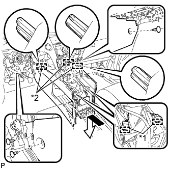
INSTALL PARKING BRAKE CONTROL PEDAL ASSEMBLY
-
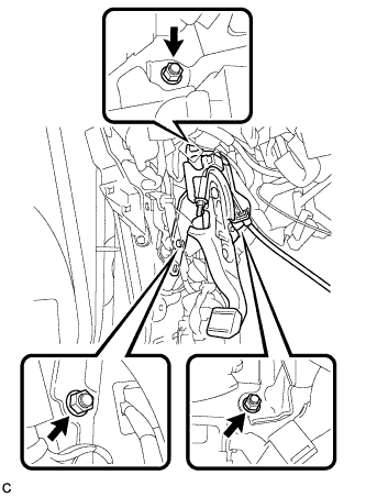
Install the parking brake control pedal assembly with the 3 nuts.
- Torque:
- 21 N*m { 214 kgf*cm, 15 ft.*lbf }
-
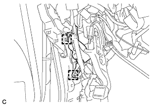
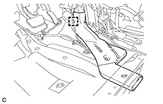
Engage the 2 clamps to install the wire harness clamp.
-
Connect the parking brake switch connector.
-
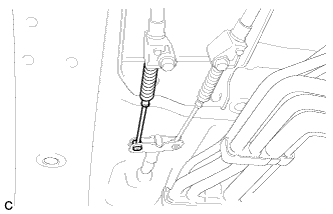
Insert the No. 1 parking brake cable assembly toward the outside of the cabin.
-
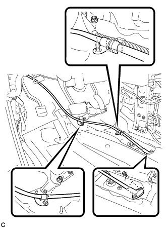
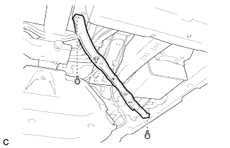
Install the No. 1 parking brake cable assembly with the 2 bolts and 2 nuts.
- Torque:
- Bolt
- 8.5 N*m { 87 kgf*cm, 75 in.*lbf }
- Nut
- 6.0 N*m { 61 kgf*cm, 53 in.*lbf }
-
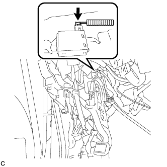
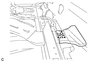
Install the clamp.
-
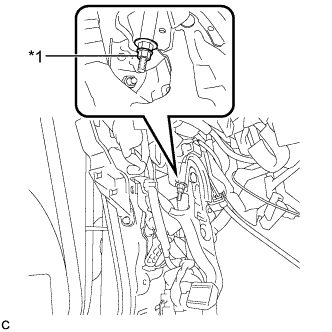
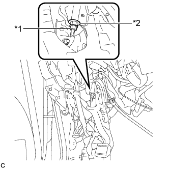
Text in Illustration *1 Lock Nut Temporarily install the lock nut.
Tech Tips
After adjusting parking brake pedal travel, tighten the lock nut.
-
-
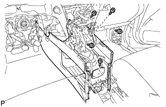
INSTALL INSTRUMENT PANEL JUNCTION BLOCK ASSEMBLY
-
Connect the connectors to the back of the instrument panel junction block assembly.
-
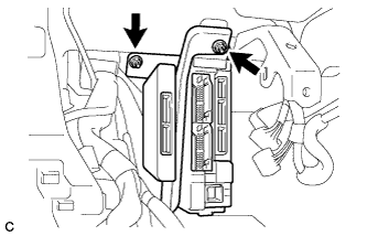
Install the instrument panel junction block assembly with the 2 nuts.
- Torque:
- 8.0 N*m { 82 kgf*cm, 71 in.*lbf }
-
Connect the connectors to the instrument panel junction block assembly.
-
-
INSTALL PARKING BRAKE EQUALIZER
-
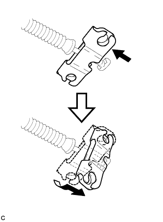
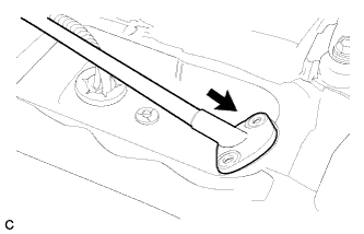
Install the parking brake equalizer to the No. 1 parking brake cable assembly as shown in the illustration.
-
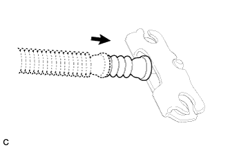
Slide the rubber boot back as shown in the illustration.
-
-
CONNECT NO. 3 PARKING BRAKE CABLE ASSEMBLY
-
Connect the No. 3 parking brake cable assembly to the parking brake equalizer.
-
-
CONNECT NO. 2 PARKING BRAKE CABLE ASSEMBLY
Tech Tips
Perform the same procedure as for the No. 3 parking brake cable assembly.
-
INSTALL REAR ENGINE SERVICE COVER ASSEMBLY
-
Install the rear engine service cover assembly with the 2 bolts.
-
-
INSTALL CENTER FRONT FLOOR COVER
-
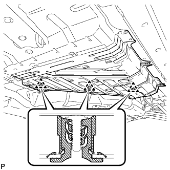
Engage the 3 clips to install the center front floor cover.
-
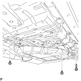
Install the 7 bolts and 2 screws.
-
-
INSTALL FRONT FLOOR FOOTREST
-
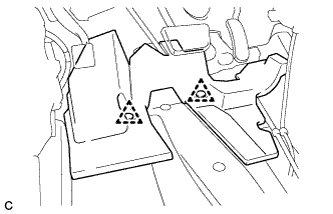
Engage the 2 clips to install the front floor footrest.
-
-
INSTALL REAR NO. 1 AIR DUCT
-
Install the rear No. 1 air duct.
-
Engage the wire harness clamp.
-
-
INSTALL REAR NO. 2 AIR DUCT
-
Install the rear No. 2 air duct with the clip.
-
Install the floor carpet.
-
-
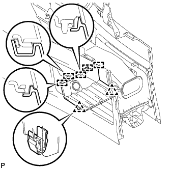
INSTALL CONSOLE BOX
-
Text in Illustration *1 Clamp *2 Guide Engage the 3 guides as shown in the illustration.
-
Engage the 2 clamps.
-
Install the 3 clips.
-
Install the console box with the 5 screws <D>.
-
-
INSTALL FRONT CONSOLE BOX COVER
-
Connect the connector.
-
Engage the 5 guides and 2 clips, and install the front console box cover.
-
-
INSTALL INSTRUMENT PANEL FINISH PANEL
-
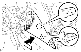
Engage the 2 guides, claw and 2 clips to install the instrument panel finish panel as shown in the illustration.
-
-
INSTALL DRIVER SIDE KNEE AIRBAG ASSEMBLY
Tech Tips
Refer to the instructions for Installation of the driver side knee airbag assembly Click here.
-
INSTALL REAR CONSOLE BOX ASSEMBLY
Tech Tips
Refer to the instructions for Installation of the rear console box assembly Click here.
-
INSTALL FRONT SEAT ASSEMBLY LH
Tech Tips
Refer to the instructions for Installation of the front seat assembly Click here.
-
ADJUST PARKING BRAKE SHOE CLEARANCE AND PARKING BRAKE PEDAL TRAVEL
-
Remove the No. 1 instrument panel under cover sub-assembly Click here.
-
Completely release the parking brake pedal.
-
Text in Illustration *1 Lock Nut *2 Adjusting Nut Loosen the lock nut and the adjusting nut to completely release the parking brake cable.
-
Remove the rear wheels.
-
Temporarily install the hub nuts to the hub bolts.
Tech Tips
Securely install the hub nuts to the rear disc.
-
Remove the parking brake shoe adjusting hole plug.
-
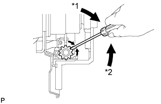
Text in Illustration *1 Expand *2 Contract Turn the shoe adjuster and expand the shoe until the disc locks.
-
Turn and contract the shoe adjuster until the disc can rotate smoothly.
Standard Returns 8 notches. -
Check that there is no brake drag against the shoe.
-
Install the parking brake shoe adjusting hole plug.
-
Turn the adjusting nut until the parking brake pedal travel is corrected to be within the specified range.
Parking brake pedal travel 7 to 10 notches at 300 N (31 kgf, 67.5 lbf) -
Text in Illustration *1 Lock Nut *2 Adjusting Nut Using a wrench or an equivalent tool, hold the adjusting nut and tighten the lock nut.
- Torque:
- 7.0 N*m { 71 kgf*cm, 62 in.*lbf }
-
Operate the parking brake pedal 3 to 4 times, and check the parking brake pedal travel.
-
Check that there is no brake drag against the shoe.
-
Remove the hub nuts from the hub bolts.
-
Install the rear wheels.
- Torque:
- 103 N*m { 1050 kgf*cm, 76 ft.*lbf }
-
Install the No. 1 instrument panel under cover sub-assembly Click here.
-
-
INSPECT BRAKE WARNING LIGHT
-
When operating the parking brake pedal, check that the brake warning light illuminates.
Standard The brake warning light always illuminates at the first click.
-