BRAKE MASTER CYLINDER (for RHD) INSTALLATION

-
INSTALL BRAKE BOOSTER GASKET
-
Install a new brake booster gasket to the brake master cylinder bracket.
-
-
INSTALL BRAKE MASTER CYLINDER BRACKET
-
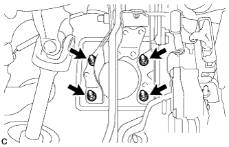
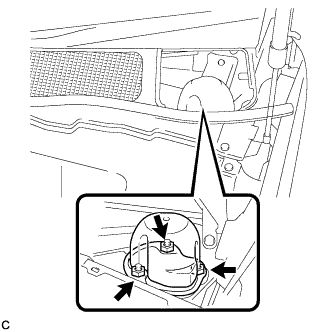
Install the brake master cylinder bracket to the body with the 4 nuts.
- Torque:
- 13 N*m { 130 kgf*cm, 9 ft.*lbf }
-
-
INSTALL BRAKE STROKE SIMULATOR CYLINDER WITH BRACKET
-
Install a new brake master cylinder gasket to the brake master cylinder bracket.
-
Install the brake stroke simulator cylinder with bracket to the brake master cylinder bracket.
-
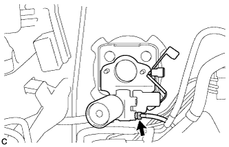
Using a union nut wrench, connect the No. 7 front brake tube to the brake stroke simulator cylinder sub-assembly.
- Torque:
- 15 N*m { 155 kgf*cm, 11 ft.*lbf }
Note
Use the formula to calculate special torque values for situations where the union nut wrench is combined with a torque wrench Click here.
-
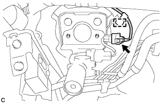
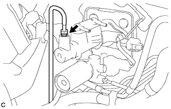
Connect the connector and engage the clamp.
-
-
INSTALL BRAKE MASTER CYLINDER SUB-ASSEMBLY
-
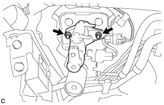
Install the brake master cylinder sub-assembly to the brake master cylinder bracket with the 2 nuts.
- Torque:
- 13 N*m { 127 kgf*cm, 9 ft.*lbf }
-
Using a union nut wrench, connect the No. 6 front brake tube to the brake master cylinder sub-assembly.
- Torque:
- 15 N*m { 155 kgf*cm, 11 ft.*lbf }
Note
Use the formula to calculate special torque values for situations where the union nut wrench is combined with a torque wrench Click here.
-
-
INSTALL BRAKE STROKE SIMULATOR TUBE
-
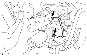
Using a union nut wrench, tighten the 2 union nuts to install the brake stroke simulator tube to the brake master cylinder sub-assembly and brake stroke simulator cylinder sub-assembly.
- Torque:
- 15 N*m { 155 kgf*cm, 11 ft.*lbf }
Note
Use the formula to calculate special torque values for situations where the union nut wrench is combined with a torque wrench Click here.
-
-
CONNECT MASTER CYLINDER PUSH ROD CLEVIS
-
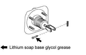
Apply lithium soap base glycol grease to the push rod pin.
-
Connect the master cylinder push rod clevis to the brake pedal with the push rod pin, and install a new clip as shown in the illustration.
-
-
INSTALL BRAKE PEDAL RETURN SPRING
-
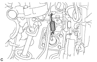
Install the brake pedal return spring between the brake pedal support sub-assembly and push rod pin.
-
-
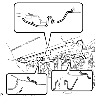
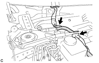
CONNECT NO. 1 RESERVOIR HOSE
-
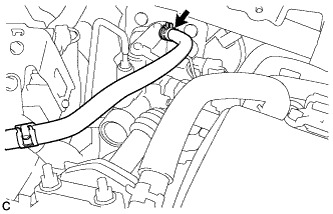
Connect the No. 1 reservoir hose to the brake master cylinder sub-assembly with the clips.
-
-
CONNECT NO. 2 RESERVOIR HOSE
-
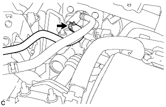
Connect the No. 2 reservoir hose to the brake master cylinder sub-assembly with the clips.
-
-
CONNECT CABLE TO NEGATIVE BATTERY TERMINAL
Note
When disconnecting the cable, some systems need to be initialized after the cable is reconnected Click here.
-
CONNECT BRAKE BOOSTER PUMP CONNECTOR
-
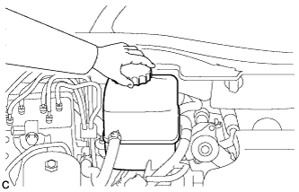
Add brake fluid into the reservoir between MAX and MIN line on the brake fluid reservoir.
Brake fluid SAE J1703 or FMVSS No. 116 DOT3 -
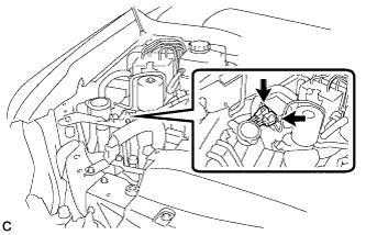
With the power switch off, connect the 2 brake booster pump connectors.
-
Turn the power switch on (IG) and check that the brake booster pump motor operates and stops.
-
Turn the power switch off.
-
-
BLEED BRAKE MASTER CYLINDER
-
Bleed brake master cylinder.
-
Remove the brake master cylinder reservoir filler cap assembly.
-
Add brake fluid into the reservoir between MAX and MIN level on the brake fluid reservoir.
Brake fluid SAE J1703 or FMVSS No. 116 DOT3 -
Connect the intelligent tester to the DLC3 and turn the power switch on (IG).
-
Turn the intelligent tester on and enter the following menus: Chassis / ABS/VSC/TRC / Utility / Air Bleeding.
-
Select the "Master Cylinder or Stroke Simulator has been removed" and bleed brake master cylinder according to the intelligent tester display.
-
After air bleeding, tighten each bleeder plug.
- Torque:
- front bleeder plug
- 8.3 N*m { 85 kgf*cm, 73 in.*lbf }
- rear bleeder plug
- 11 N*m { 110 kgf*cm, 8 ft.*lbf }
-
-
Clear the DTCs Click here.
-
Turn the intelligent tester off and turn the power switch off.
-
Inspect for brake fluid leaks.
-
Adjust the brake fluid level in the reservoir Click here.
-
-
INSPECT AND ADJUST BRAKE PEDAL
Tech Tips
-
CHECK BRAKE MASTER CYLINDER WITH INTELLIGENT TESTER
-
Check the brake master cylinder and stroke simulator Click here.
-
-
CHECK MASTER CYLINDER PRESSURE SENSOR SIGNAL
-
Check the pressure sensor signal Click here.
-
-
CHECK FOR DTC
-
Check for DTCs. If any DTC is output, perform the troubleshooting for that DTC Click here.
-
-
INSTALL NO. 1 INSTRUMENT PANEL UNDER COVER SUB-ASSEMBLY
-
Engage each clamp.
-
Connect each connector.
-
Engage the claw and 2 guides.
-
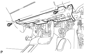
Install the No. 1 instrument panel under cover sub- assembly with the 2 screws <D>.
-
-
INSTALL OUTER COWL TOP PANEL SUB-ASSEMBLY
-
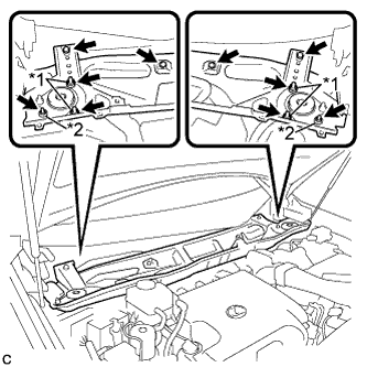
Install the outer cowl top panel sub-assembly with the 4 bolts, 4 nuts*1 and 2 nuts*2.
- Torque:
- Nut*1
- 85 N*m { 867 kgf*cm, 63 ft.*lbf }
- Nut*2
- 5.5 N*m { 56 kgf*cm, 49 in.*lbf }
- Bolt
- 5.5 N*m { 56 kgf*cm, 49 in.*lbf }
-
Engage the grommet.
-
Connect the connector (w/ Windshield Deicer).
-
-
INSTALL FRONT SHOCK ABSORBER CAP LH (w/ Air Suspension)
-
Install the front shock absorber cap with the 3 nuts.
- Torque:
- 14 N*m { 143 kgf*cm, 10 ft.*lbf }
-
-
INSTALL FRONT SHOCK ABSORBER CAP RH (w/ Air Suspension)
Tech Tips
Use the same procedure for the LH side and RH side.
-
INSTALL WINDSHIELD WIPER MOTOR AND LINK ASSEMBLY
Tech Tips
Refer to the instructions for Installation of the windshield wiper motor and link assembly Click here.
-
INSTALL REAR DECK FLOOR BOX
-

Install the rear deck floor box with the 3 clips.
-