BRAKE PEDAL (for RHD) ADJUSTMENT

-
INSPECT AND ADJUST BRAKE PEDAL HEIGHT
-
Check the brake pedal height.
-
Turn back the carpet.
-
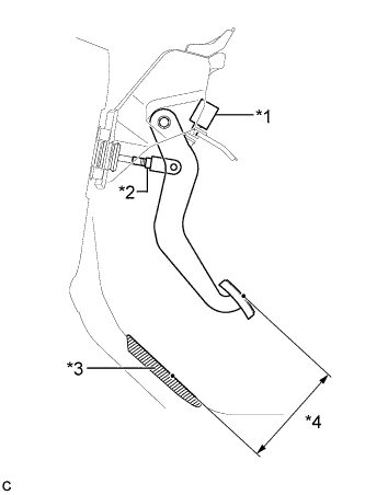
Text in Illustration *1 Stop Light Switch Assembly *2 Push Rod Clevis Lock Nut *3 No. 2 Dash Panel Insulator Pad *4 Pedal Height Measure the shortest distance between the brake pedal surface and No. 2 dash panel insulator pad.
Pedal height from No. 2 dash panel insulator pad 156.2 to 166.2 mm (6.15 to 6.54 in.)
-
-
Adjust the brake pedal height.
-
Remove the stop light switch assembly Click here.
-
Loosen the push rod clevis lock nut.
-
Adjust the brake pedal height by turning the push rod.
Pedal height from No. 2 dash panel insulator pad 156.2 to 166.2 mm (6.15 to 6.54 in.) -
Tighten the push rod clevis lock nut.
- Torque:
- 26 N*m { 265 kgf*cm, 19 ft.*lbf }
-
Install and adjust the stop light switch assembly Click here.
Note
Do not depress the brake pedal.
-
-
-
ADJUST BRAKE PEDAL STROKE SENSOR ASSEMBLY
-
When reusing the brake pedal stroke sensor assembly:
-
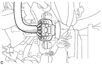
Connect the sensor connector.
-
Connect the cable to the negative (-) battery terminal.
-
Connect the intelligent tester to the DLC3.
-
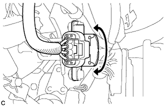
Turn the power switch on (IG). Reading the value of the stroke sensor shown in Data List, turn the sensor slowly to the right and left to adjust the output voltage to the standard voltage.
Standard Voltage Tester Display Measurement Item/Range Normal Condition Diagnostic Note Stroke Sensor Stroke sensor /
min.: 0 V, max.: 5 V
When brake pedal is released:
0.8 to 1.2 V
- -
Tighten the 2 bolts.
- Torque:
- 8.5 N*m { 87 kgf*cm, 75 in.*lbf }
Note
Do not depress the brake pedal after turning the power switch on (IG).
-
Turn the power switch off.
-
Disconnect the cable from the negative (-) battery terminal.
Note
After the power switch is turned off, the display and navigation module display (HDD navigation system) records various types of memory and settings. As a result, after turning the power switch off, make sure to wait for the time specified in the following table before disconnecting the cable from the negative (-) battery terminal.
Waiting Time before Disconnecting Cable from Negative (-) Battery Terminal Specification Waiting Time w/o Telematics transceiver 60 sec. w/ Telematics transceiver 120 sec. -
Disconnect the intelligent tester.
-
-
-
INSPECT BRAKE PEDAL FREE PLAY
-
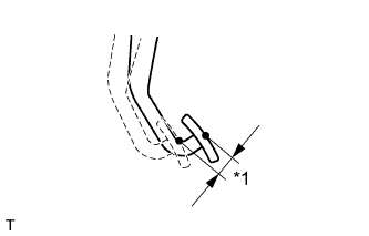
Text in Illustration *1 Brake Pedal Free Play Depress the brake pedal until a slight resistance is felt. Measure the brake pedal free play as shown in the illustration.
Pedal free play 1.0 to 2.0 mm (0.0394 to 0.0787 in.) If the pedal free play is not as specified, check the stop light switch clearance Click here. If the pedal free play is as specified, proceed to the Inspect Brake Pedal Reserve Distance procedure.
-
-
INSPECT BRAKE PEDAL RESERVE DISTANCE
Tech Tips
Measure the distance at the same point used for the brake pedal height inspection.
-
Release the parking brake pedal.
-
With the power switch on (READY), depress the brake pedal and measure the pedal reserve distance.
Pedal reserve distance from the No. 2 dash panel insulator pad at 500 N (51 kgf, 112 lbf) More than 103 mm (4.06 in.) If the distance is not as specified, troubleshoot the brake system Click here.
-