BRAKE CONTROL POWER SUPPLY REMOVAL

Note
While the battery is connected, even if the power switch is off, the brake control system activates when the brake pedal is depressed or any door courtesy switch is turned on. Therefore, when servicing the brake system components, do not depress the brake pedal or open/close the doors while the battery is connected.
-
PRECAUTION (w/ Navigation System for HDD)
Note
After the power switch is turned off, the display and navigation module display (HDD navigation system) records various types of memory and settings. As a result, after turning the power switch off, make sure to wait for the time specified in the following table before disconnecting the cable from the negative (-) battery terminal.
Waiting Time before Disconnecting Cable from Negative (-) Battery Terminal Specification Waiting Time w/o Telematics transceiver 60 sec. w/ Telematics transceiver 120 sec. -
REMOVE REAR DECK FLOOR BOX
-

Remove the 3 clips and the rear deck floor box.
-
-
DISCONNECT CABLE FROM NEGATIVE BATTERY TERMINAL
Note
When disconnecting the cable, some systems need to be initialized after the cable is reconnected Click here.
-
REMOVE DECK BOARD SUB-ASSEMBLY
-
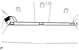
Disengage the 3 fasteners as shown in the illustration.
-
for Compact Spare Tire:
-
Remove the 2 bolts and remove the deck board sub-assembly.
-
-
for Full Size Spare Tire:
-
Remove the 2 bolts and remove the deck board sub-assembly.
-
-
-
REMOVE SPARE WHEEL COVER ASSEMBLY (for Compact Spare Tire)
-
Remove the spare wheel cover assembly.
-
-
REMOVE NO. 4 REAR FLOOR BOARD (for Compact Spare Tire)
-
Disengage the 2 guides and remove the No. 4 rear floor board.
-
-
REMOVE NO. 4 REAR FLOOR BOARD (for Full Size Spare Tire)
-
Disengage the 2 guides and remove the No. 4 rear floor board.
-
-
REMOVE NO. 3 REAR FLOOR BOARD (for Compact Spare Tire)
-
Disengage the 2 guides and remove the No. 3 rear floor board.
-
-
REMOVE NO. 3 REAR FLOOR BOARD (for Full Size Spare Tire)
-
Disengage the 2 guides and remove the No. 3 rear floor board.
-
-
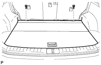
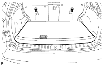
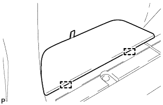
REMOVE TONNEAU COVER ASSEMBLY
-
Remove the tonneau cover assembly.
-
-
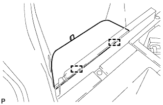
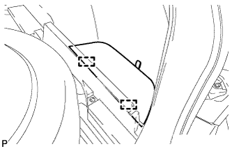
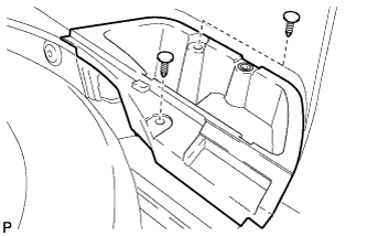
REMOVE DECK SIDE TRIM BOX LH (for Compact Spare Tire)
-
Remove the 2 clips and the deck side trim box LH.
-
-
REMOVE DECK SIDE TRIM BOX LH (for Full Size Spare Tire)
-
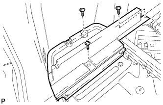
Remove the 3 clips and the deck side trim box LH.
-
-
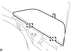
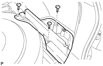
REMOVE DECK SIDE TRIM BOX RH (for Compact Spare Tire)
-
Remove the 2 clips and deck side trim box RH.
-
-
REMOVE DECK SIDE TRIM BOX RH (for Full Size Spare Tire)
-
Remove the 3 clips and the deck side trim box RH.
-
-
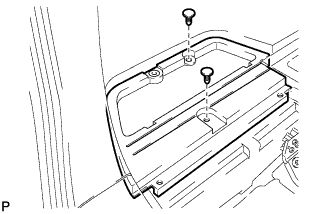
REMOVE FRONT DECK FLOOR BOX
-
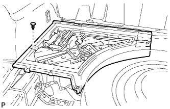
Remove the clip and the front deck floor box.
-
-
REMOVE REAR FLOOR FINISH PLATE
-
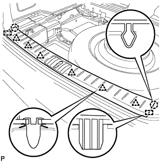
Disengage the 2 claws, 6 clips and 2 guides, and remove the rear floor finish plate.
-
-
REMOVE BRAKE CONTROL POWER SUPPLY WITH BRACKET
-
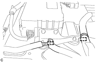
Remove the 2 clamps.
-
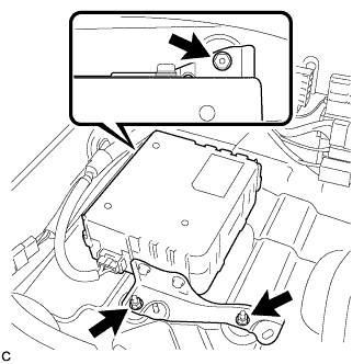
Remove the 3 nuts and the brake control power supply with bracket.
CAUTION:
Immediately after removing the brake control power supply from the vehicle, there may be an electrical charge left in the internal capacitor. If planning to inspect the inside of the brake control power supply, leave it as is for more than 24 hours (to discharge it) after removing it from the vehicle. Then, perform the inspection.
-
Disconnect the connector.
-
-
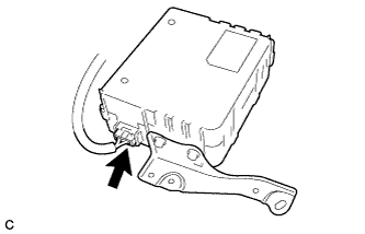
REMOVE BRAKE CONTROL POWER SUPPLY ASSEMBLY
-
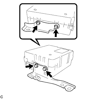
Remove the 4 bolts, No. 1 control power supply bracket and No. 2 control power supply bracket.
Note
Do not drop the brake control power supply. If the brake control power supply has been dropped, replace the brake control power supply with a new one.
-