BRAKE PEDAL STROKE SENSOR INSTALLATION

Note
While the battery is connected, even if the power switch is off, the brake control system activates when the brake pedal is depressed or any door courtesy switch is turned on. Therefore, when servicing the brake system components, do not depress the brake pedal or open/close the doors while the battery is connected.
-
INSPECT AND ADJUST BRAKE PEDAL HEIGHT (for LHD)
Tech Tips
-
INSPECT AND ADJUST BRAKE PEDAL HEIGHT (for RHD)
Tech Tips
-
INSTALL BRAKE PEDAL STROKE SENSOR ASSEMBLY (for LHD)
Note
Do not drop the sensor. If the sensor has been dropped, replace the brake pedal stroke sensor with a new one.
-
When installing a new brake pedal stroke sensor assembly:
Note
Do not break the sensor lever set pin before installing the brake pedal stroke sensor with the bolts.
-
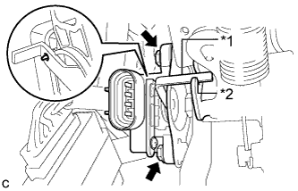
Text in Illustration *1 Lever *2 Groove Install a new sensor with the 2 bolts.
- Torque:
- 8.5 N*m { 87 kgf*cm, 75 in.*lbf }
Note
-
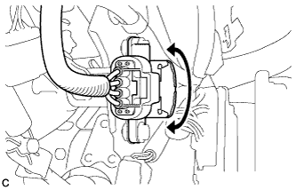
Engage the sensor lever with the brake pedal groove.
-
Check that there is no foreign matter attached to the contact surface of the sensor.
-
Check that the tip of the sensor lever is protruding from the brake pedal groove.
-
Firmly depress the brake pedal and break the sensor lever set pin.
-
Remove the broken lever set pin.
-
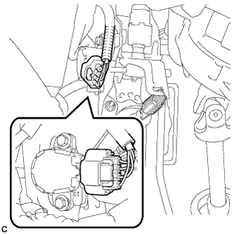
Connect the sensor connector.
-
-
When reusing the brake pedal stroke sensor assembly:
-
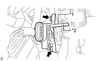
Text in Illustration *1 Lever *2 Groove Temporarily install the sensor with the 2 bolts.
Note
-
Engage the sensor lever with the brake pedal groove.
-
Check that there is no foreign matter attached to the contact surface of the sensor.
-
-
-
-
INSTALL BRAKE PEDAL STROKE SENSOR ASSEMBLY (for RHD)
Note
Do not drop the sensor. If the sensor has been dropped, replace the brake pedal stroke sensor with a new one.
-
When installing a new brake pedal stroke sensor assembly:
Note
Do not break the sensor lever set pin before installing the brake pedal stroke sensor with the bolts.
-
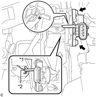
Text in Illustration *1 Lever *2 Groove Install a new sensor with the 2 bolts.
- Torque:
- 8.5 N*m { 87 kgf*cm, 75 in.*lbf }
Note
-
Engage the sensor lever with the brake pedal groove.
-
Check that there is no foreign matter attached to the contact surface of the sensor.
-
Check that the tip of the sensor lever is protruding from the brake pedal groove.
-
Firmly depress the brake pedal and break the sensor lever set pin.
-
Remove the broken lever set pin.
-
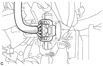
Connect the sensor connector.
-
-
When reusing the brake pedal stroke sensor assembly:
-
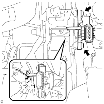
Text in Illustration *1 Lever *2 Groove Temporarily install the sensor with the 2 bolts.
Note
-
Engage the sensor lever with the brake pedal groove.
-
Check that there is no foreign matter attached to the contact surface of the sensor.
-
-
-
-
ADJUST BRAKE PEDAL STROKE SENSOR ASSEMBLY (for LHD)
-
When reusing the brake pedal stroke sensor assembly:
-
Connect the sensor connector.
-
Connect the cable to the negative (-) battery terminal.
-
Connect the intelligent tester to the DLC3.
-
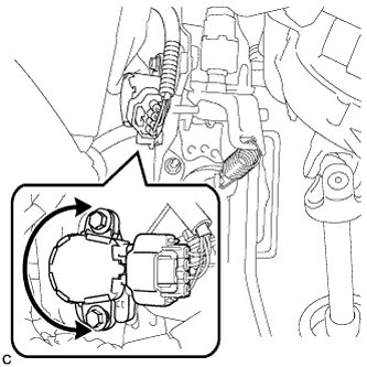
Turn the power switch on (IG). Reading the value of the stroke sensor shown in Data List, turn the sensor slowly to the right and left to adjust the output voltage to the standard voltage.
Standard Voltage Tester Display Measurement Item/Range Normal Condition Diagnostic Note Stroke Sensor Stroke sensor /
min.: 0 V, max.: 5 V
When brake pedal is released:
0.8 to 1.2 V
- -
Tighten the 2 bolts.
- Torque:
- 8.5 N*m { 87 kgf*cm, 75 in.*lbf }
Note
Do not depress the brake pedal after turning the power switch on (IG).
-
Turn the power switch off.
-
Disconnect the cable from the negative (-) battery terminal.
Note
After the power switch is turned off, the display and navigation module display (HDD navigation system) records various types of memory and settings. As a result, after turning the power switch off, make sure to wait for the time specified in the following table before disconnecting the cable from the negative (-) battery terminal.
Waiting Time before Disconnecting Cable from Negative (-) Battery Terminal Specification Waiting Time w/o Telematics transceiver 60 sec. w/ Telematics transceiver 120 sec. -
Disconnect the intelligent tester.
-
-
-
ADJUST BRAKE PEDAL STROKE SENSOR ASSEMBLY (for RHD)
-
When reusing the brake pedal stroke sensor assembly:
-
Connect the sensor connector.
-
Connect the cable to the negative (-) battery terminal.
-
Connect the intelligent tester to the DLC3.
-
Turn the power switch on (IG). Reading the value of the stroke sensor shown in Data List, turn the sensor slowly to the right and left to adjust the output voltage to the standard voltage.
Standard Voltage Tester Display Measurement Item/Range Normal Condition Diagnostic Note Stroke Sensor Stroke sensor /
min.: 0 V, max.: 5 V
When brake pedal is released:
0.8 to 1.2 V
- -
Tighten the 2 bolts.
- Torque:
- 8.5 N*m { 87 kgf*cm, 75 in.*lbf }
Note
Do not depress the brake pedal after turning the power switch on (IG).
-
Turn the power switch off.
-
Disconnect the cable from the negative (-) battery terminal.
Note
After the power switch is turned off, the display and navigation module display (HDD navigation system) records various types of memory and settings. As a result, after turning the power switch off, make sure to wait for the time specified in the following table before disconnecting the cable from the negative (-) battery terminal.
Waiting Time before Disconnecting Cable from Negative (-) Battery Terminal Specification Waiting Time w/o Telematics transceiver 60 sec. w/ Telematics transceiver 120 sec. -
Disconnect the intelligent tester.
-
-
-
INSTALL DRIVER SIDE KNEE AIRBAG ASSEMBLY
Tech Tips
Refer to the procedure up to Install Driver Side Knee Airbag Assembly Click here.
-
CHECK AND CLEAR DTC
-
Check and clear the DTCs Click here.
-
-
PERFORM LINEAR VALVE OFFSET LEARNING
-
Perform linear valve offset learning Click here.
-