REAR SPEED SENSOR (for 2WD) INSTALLATION

Tech Tips
-
Use the same procedure for the RH side and LH side.
-
The following procedure is for the LH side.
-
The rear speed sensor is a component of the rear axle hub and bearing assembly. If the sensor malfunctions, replace the rear axle hub and bearing assembly.
-
If the sensor rotor needs to be replaced, replace it together with the rear axle hub and bearing assembly.
-
INSTALL REAR AXLE HUB AND BEARING ASSEMBLY
-
Install the rear axle hub and bearing assembly Click here.
Tech Tips
-
The rear speed sensor is a component of the rear axle hub and bearing assembly. If the sensor malfunctions, replace the rear axle hub and bearing assembly.
-
If the sensor rotor needs to be replaced, replace it together with the rear axle hub and bearing assembly.
-
-
-
INSPECT REAR AXLE HUB BEARING LOOSENESS
-
Using a dial indicator, check for looseness near the center of the rear axle hub.
Maximum looseness 0 mm (0 in.) Note
-
Ensure that the dial indicator is set perpendicular to the measurement surface.
-
Keep the magnet of the dial indicator away from the rear axle hub and bearing assembly.
Tech Tips
If the looseness exceeds the maximum, replace the rear axle hub and bearing assembly.
-
-
-
INSPECT REAR AXLE HUB RUNOUT
-
Using a dial indicator, check for runout on the surface of the rear axle hub outside the rear axle hub bolt.
Maximum runout 0.08 mm (0.00314 in.) Note
-
Ensure that the dial indicator is set perpendicular to the measurement surface.
-
Keep the magnet of the dial indicator away from the rear axle hub and bearing assembly.
Tech Tips
If the runout exceeds the maximum, replace the rear axle hub and bearing assembly.
-
-
-
INSTALL REAR DISC
-
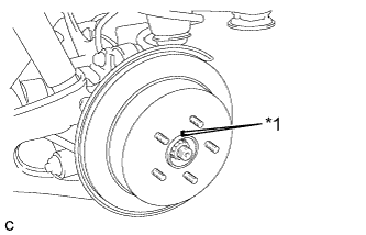
Text in Illustration *1 Matchmark Align the matchmarks and install the rear disc.
Note
When replacing the rear disc with a new one, select the installation position where the rear disc has minimal runout.
-
-
INSTALL PARKING BRAKE SHOE ADJUSTING HOLE PLUG
-
Install the parking brake shoe adjusting hole plug.
-
-
INSTALL REAR DISC BRAKE CALIPER ASSEMBLY
-
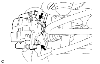
Install the rear disc brake caliper assembly with the 2 bolts.
- Torque:
- 78 N*m { 799 kgf*cm, 58 ft.*lbf }
-
-
INSTALL REAR SPEED SENSOR WIRE
-
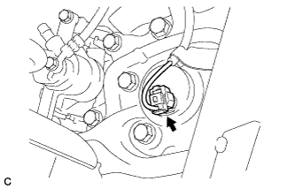
Connect the connector to the rear speed sensor.
-
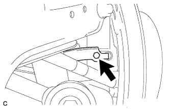
Install the No. 1 bracket with the bolt.
- Torque:
- 8.0 N*m { 82 kgf*cm, 71 in.*lbf }
-
-
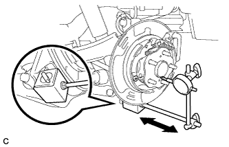
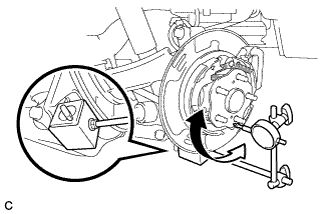
INSTALL REAR SUSPENSION ARM COVER
-
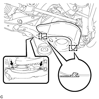
Insert the 2 guides of the rear suspension arm cover to the rear No. 2 suspension arm assembly.
-
Install the rear suspension arm cover to the rear No. 2 suspension arm assembly with the 2 bolts as shown in the illustration.
- Torque:
- 12 N*m { 122 kgf*cm, 9 ft.*lbf }
Note
Make sure that the 2 guides of rear suspension arm cover are inserted.
-
-
INSTALL REAR WHEEL
- Torque:
- 103 N*m { 1050 kgf*cm, 76 ft.*lbf }
-
CONNECT CABLE TO NEGATIVE BATTERY TERMINAL
Note
When disconnecting the cable, some systems need to be initialized after the cable is reconnected Click here.
-
INSTALL REAR DECK FLOOR BOX
-

Install the rear deck floor box with the 3 clips.
-
-
INSPECT AND ADJUST REAR WHEEL ALIGNMENT
Tech Tips
-
CHECK FOR SPEED SENSOR SIGNAL
Tech Tips