ELECTRONICALLY CONTROLLED BRAKE SYSTEM Skid Control Buzzer Circuit
DESCRIPTION
The skid control buzzer sounds during VSC operation.
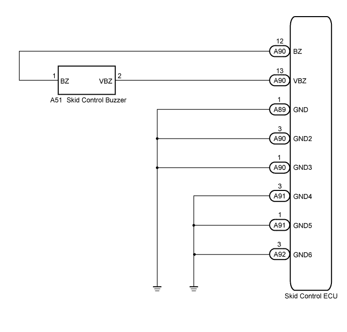
WIRING DIAGRAM
INSPECTION PROCEDURE
Note
When replacing the skid control ECU, perform initialization and calibration of the linear solenoid valve Click here.
PROCEDURE
-
PERFORM ACTIVE TEST USING INTELLIGENT TESTER (SKID CONTROL BUZZER)
-
Connect the intelligent tester to the DLC3.
-
Turn the power switch on (IG).
-
Select the Active Test on the intelligent tester Click here.
ABS/VSC/TRC Tester Display Test Part Control Range Diagnostic Note Buzzer Skid control buzzer Buzzer ON/OFF Buzzer can be heard -
Check that the buzzer sounds/stops when turning the skid control buzzer on/off using the intelligent tester.
Result Result Proceed to Buzzer does not sound or sounds constantly A Buzzer sounds/stops B Tech Tips
If troubleshooting has been carried out according to Problem Symptoms Table, refer back to the table and proceed to the next step Click here.
B 
END
A 
-
-
INSPECT SKID CONTROL ECU (BUZZER OUTPUT)
-
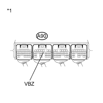
Text in Illustration *1 Component with harness connected
(Skid Control ECU)
Turn the power switch off.
-
Turn the power switch on (IG).
-
Measure the voltage according to the value(s) in the table below.
Standard Voltage Tester Connection Switch Condition Specified Condition A90-13 (VBZ) - Body ground Power switch on (IG) 9.1 to 15 V
NG
REPLACE SKID CONTROL ECU Click here
OK
-
-
INSPECT SKID CONTROL BUZZER
-
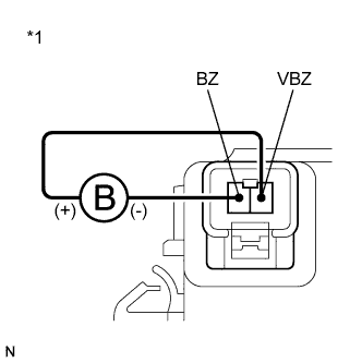
Text in Illustration *1 Component without harness connected
(Skid Control Buzzer)
Turn the power switch off.
-
Disconnect the skid control buzzer connector.
-
Apply battery negative voltage to terminal 1, and battery positive voltage to terminal 2 of the skid control buzzer, and then check that the buzzer sounds.
OK The skid control buzzer sounds.
NG
REPLACE SKID CONTROL BUZZER Click here
OK
-
-
CHECK HARNESS AND CONNECTOR (SKID CONTROL ECU - SKID CONTROL BUZZER)
-
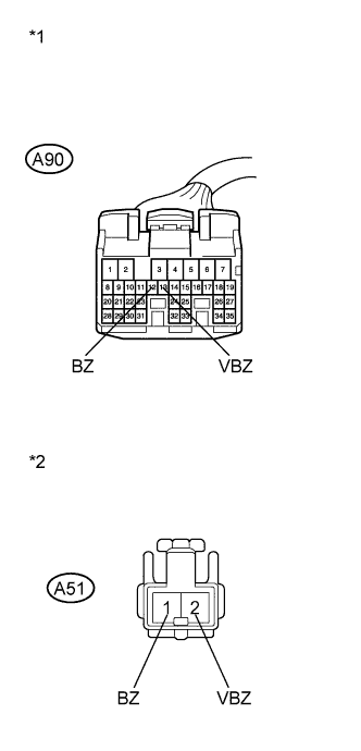
Text in Illustration *1 Front view of wire harness connector
(to Skid Control ECU)
*2 Front view of wire harness connector
(to Skid Control Buzzer)
Disconnect the skid control ECU connector.
-
Measure the resistance according to the value(s) in the table below.
Standard Resistance Tester Connection Condition Specified Condition A90-12 (BZ) - A51-1 (BZ) Always Below 1 Ω A90-12 (BZ) - Body ground Always 10 kΩ or higher A90-13 (VBZ) - A51-2 (VBZ) Always Below 1 Ω A90-13 (VBZ) - Body ground Always 10 kΩ or higher
NG
REPAIR OR REPLACE HARNESS OR CONNECTOR
OK
-
-
INSPECT SKID CONTROL ECU (GND TERMINAL)
-
Disconnect the skid control ECU connectors.
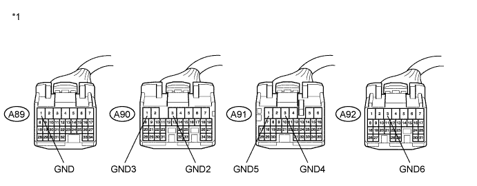
Text in Illustration *1 Front view of wire harness connector
(to Skid Control ECU)
- - -
Measure the resistance according to the value(s) in the table below.
Standard Resistance Tester Connection Condition Specified Condition A89-1 (GND) - Body ground Always Below 1 Ω A90-3 (GND2) - Body ground Always Below 1 Ω A90-1 (GND3) - Body ground Always Below 1 Ω A91-3 (GND4) - Body ground Always Below 1 Ω A91-1 (GND5) - Body ground Always Below 1 Ω A92-3 (GND6) - Body ground Always Below 1 Ω Tech Tips
If troubleshooting has been carried out according to Problem Symptoms Table, refer back to the table and proceed to the next step before replacing the part Click here.
NG
REPAIR OR REPLACE HARNESS OR CONNECTOR (GND CIRCUIT)
OK 
REPLACE SKID CONTROL ECU Click here
-